2.0 Version: 2D Export #
The 2D Export workspace provides multiple professional drawing styles and customization tools to create print-ready floor plans.
Users can add annotations, adjust drawing appearance, configure sheet templates, and download the final floor plan in their preferred presentation format.
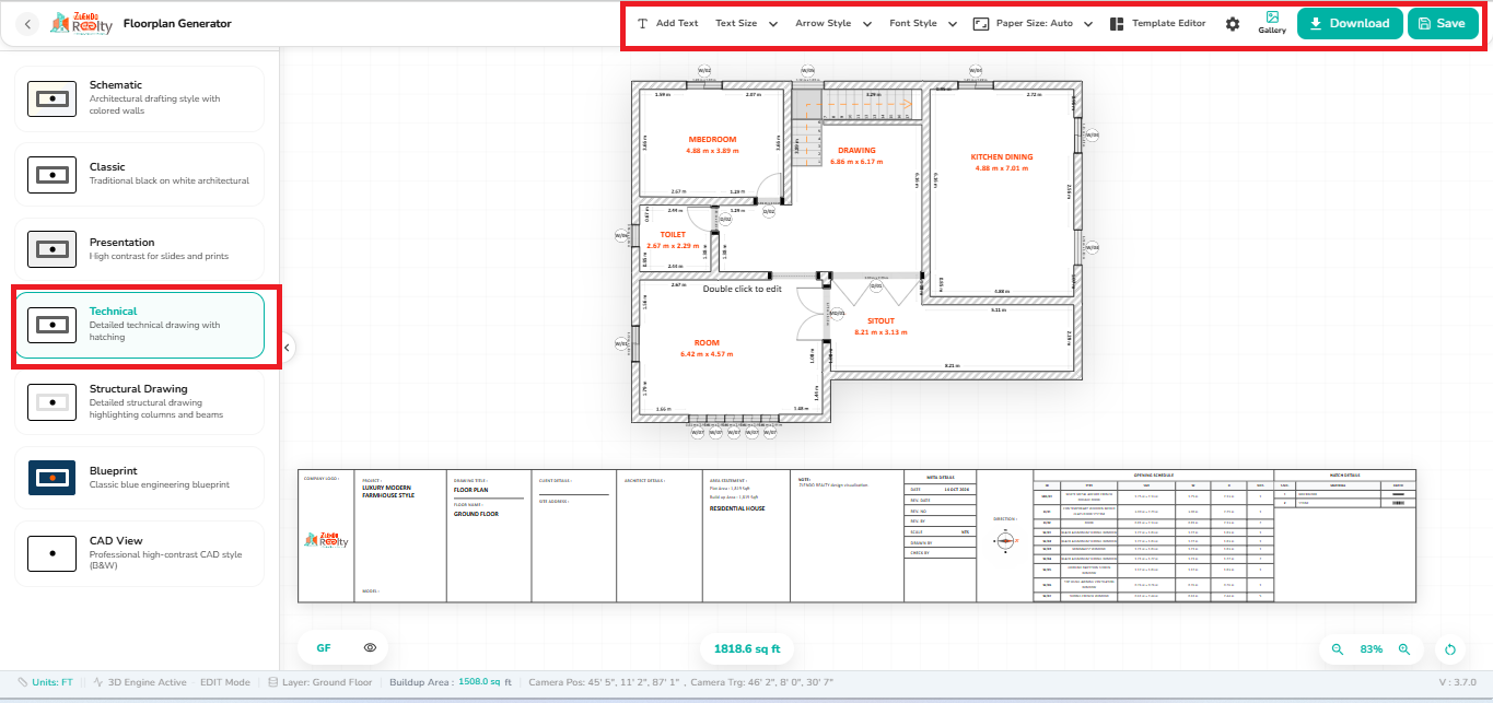
The Technical View is loaded by default, ensuring a detailed architectural drawing suitable for documentation and construction references.
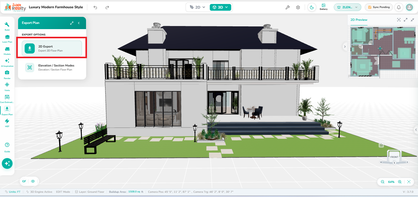
1. Accessing 2D Export #
- Open the Export Plan panel.
- Click 2D Export under Export Options.
- The editor switches to Technical View by default and displays the floor plan on the drawing sheet.
2. Available Export Styles #
The left panel provides multiple drawing presentation styles:
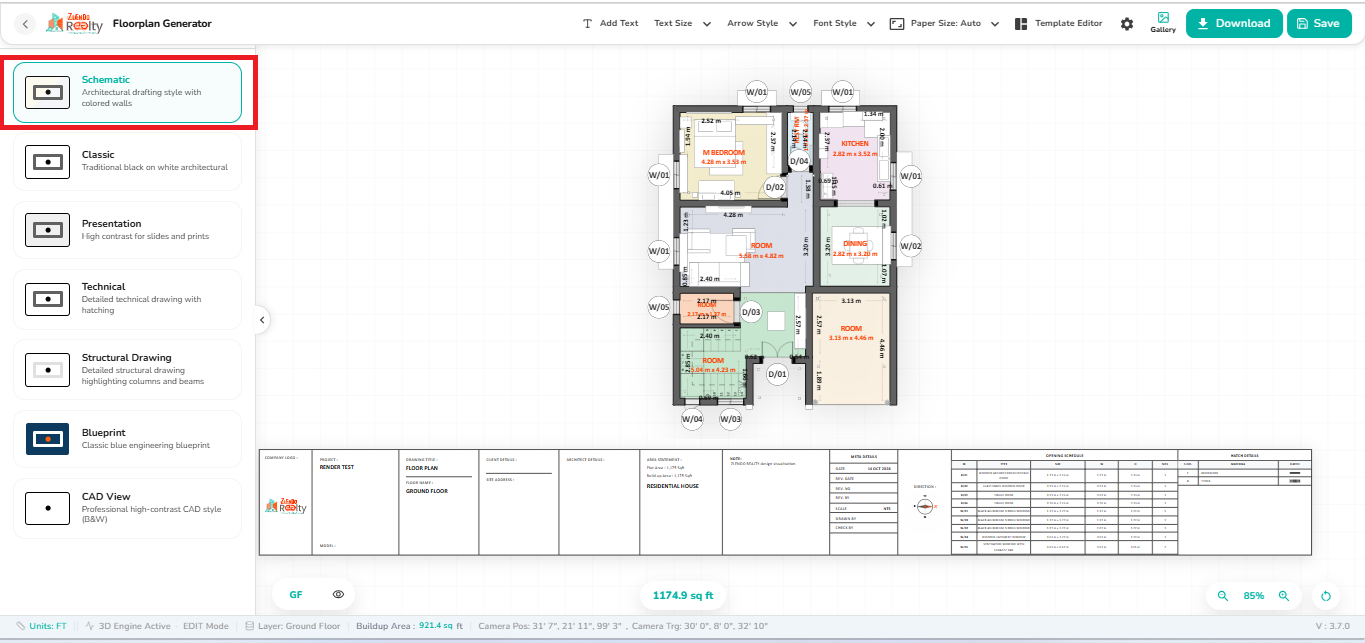
- Schematic: Architectural drafting style with colored walls.
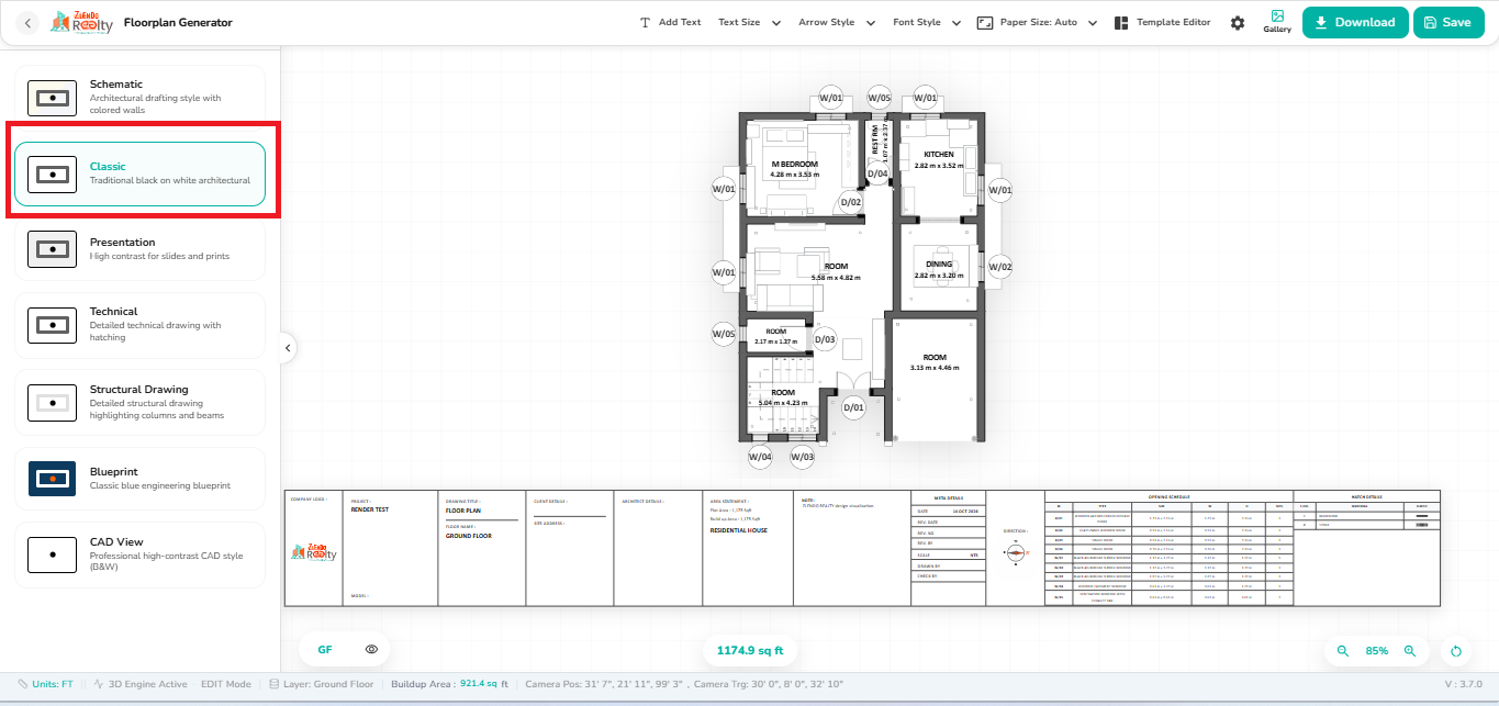
- Classic: Traditional black-and-white architectural drawing.
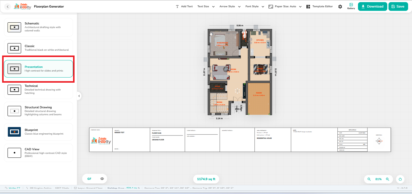
- Presentation: High-contrast layout suitable for presentations and printing.
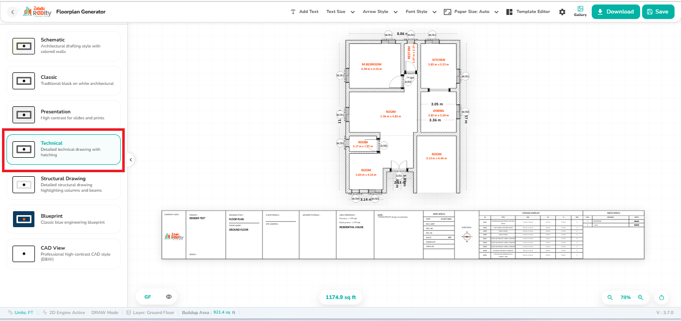
- Technical (Default): Detailed technical drawing with wall hatching and dimensions.
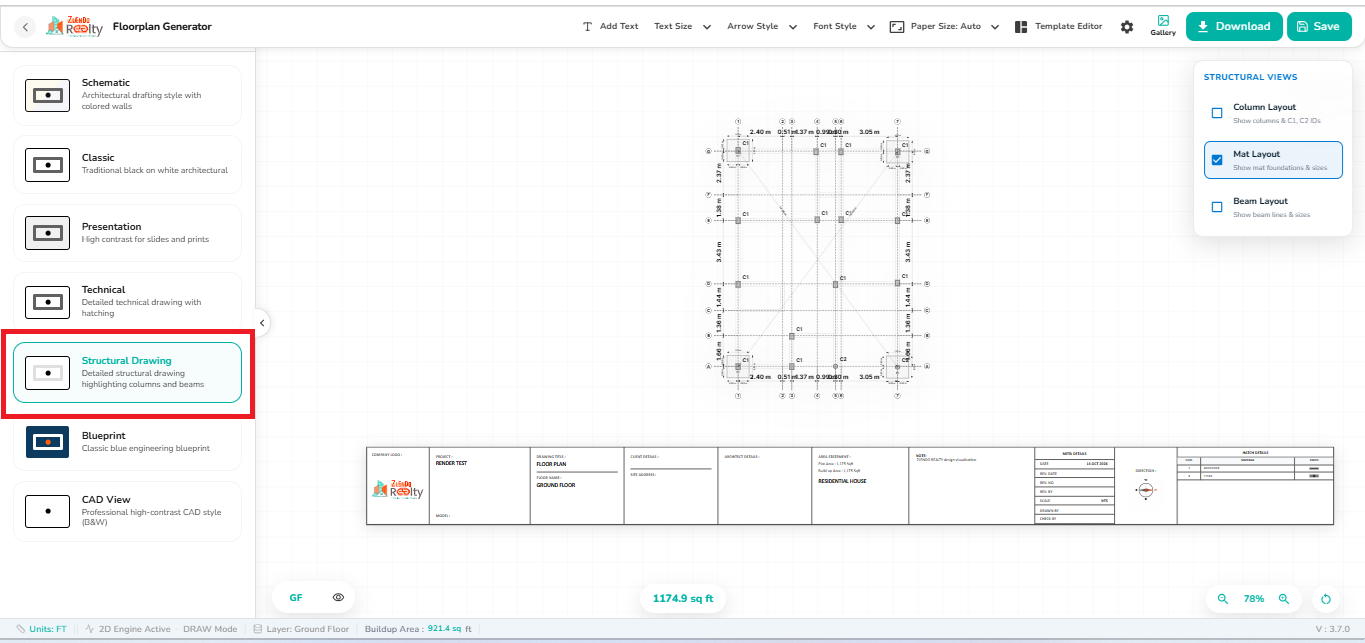
- Structural Drawing: Highlights structural elements such as columns and beams.
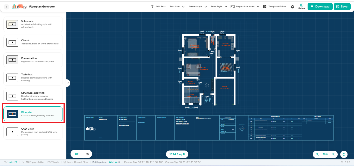
- Blueprint: Engineering-style blue background drawing.
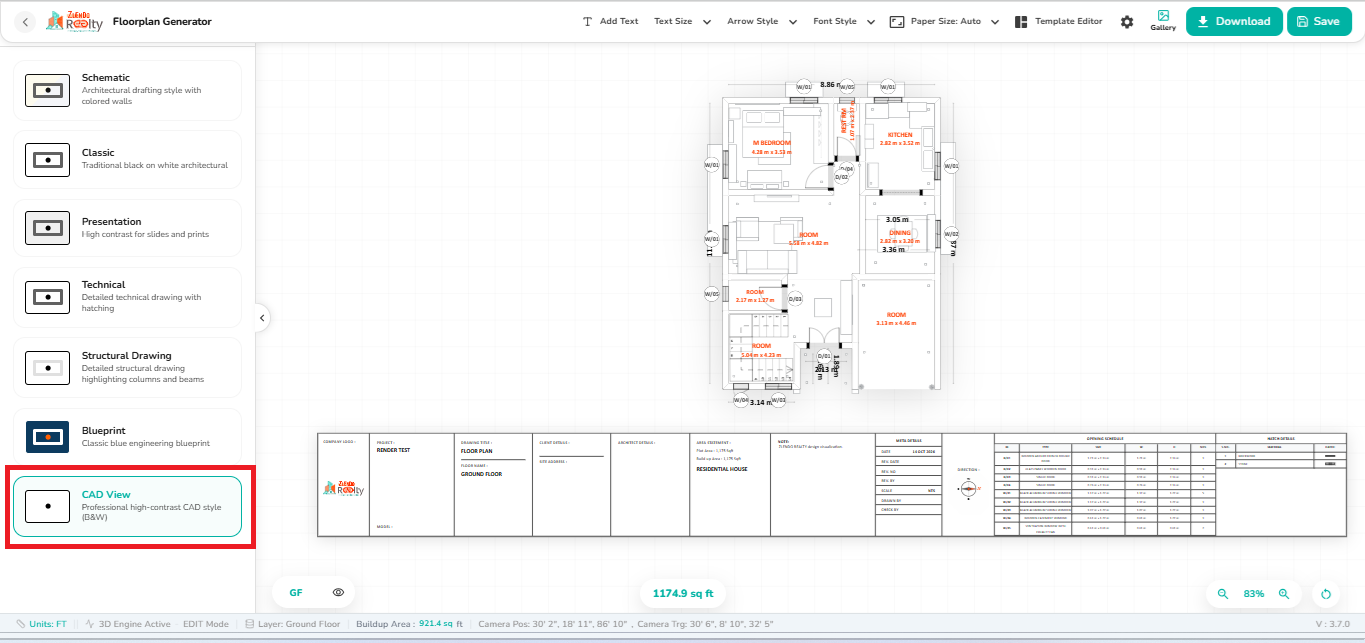
- CAD View: Professional monochrome CAD-style output.
Schematic #
Architectural drafting style with colored walls.
Classic #
Traditional black-and-white architectural drawing.
Presentation #
High-contrast layout suitable for presentations and printing.
Technical (Default) #
Detailed technical drawing with wall hatching and dimensions.
Structural Drawing #
Highlights structural elements such as columns and beams.
Blueprint #
Engineering-style blue background drawing.
CAD View #
Professional monochrome CAD-style output.
3. Toolbar Options #
The top toolbar provides tools to customize the exported drawing.
Add Text #
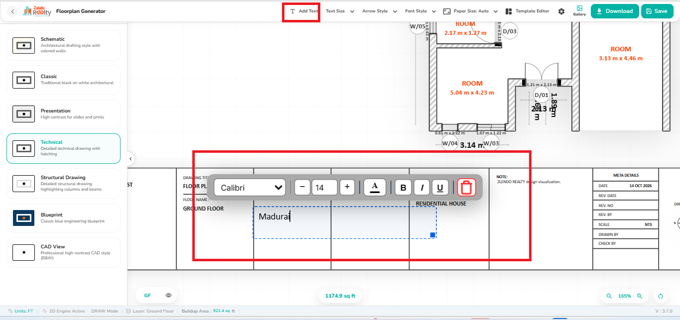
The Add Text tool allows users to insert and format custom annotations, notes, labels, or project information directly on the drawing sheet before exporting the final 2D floor plan.
Steps #
- Click Add Text from the top toolbar.
- Click anywhere on the drawing sheet to place a text box.
- Enter the required text or annotation.
- Use the formatting toolbar to select Font Style, Font Size, Bold, Italic, or Underline options.
- Drag and position the text box as needed.
- Click the Delete icon to remove the selected text.
- Save or download the drawing after completing the annotations.
Text Size #
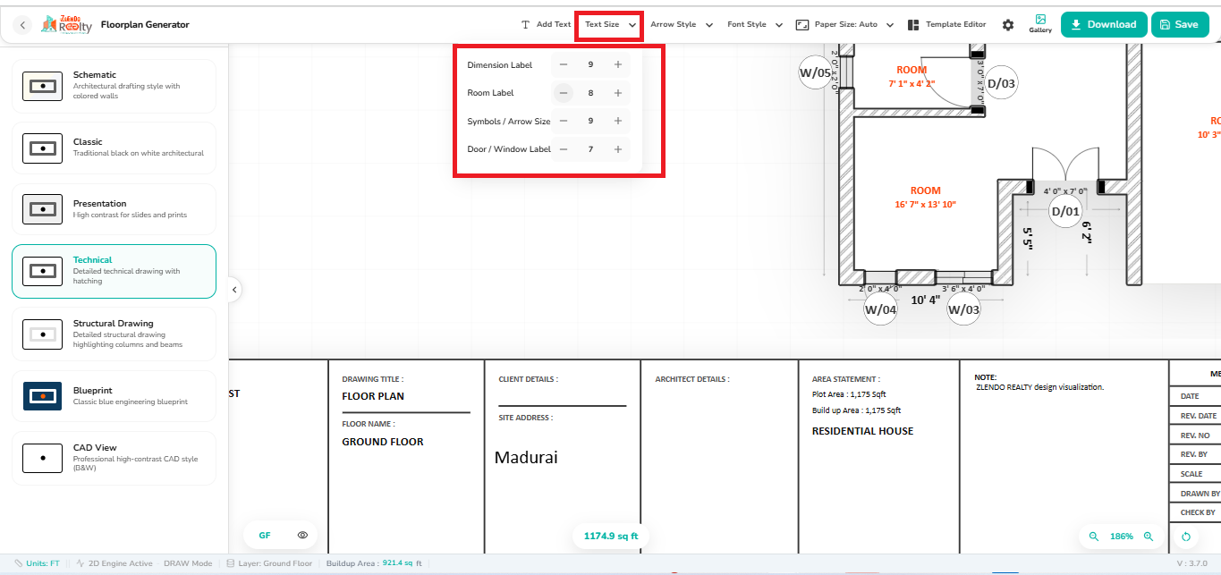
Adjust annotation text size using Text Size.
Steps #
- Click Text Size from the top toolbar to open the Text Size Settings panel.
- Adjust Dimension Labels, Room Labels, Symbols / Arrow Size, and Door / Window Labels.
- Use the (+) button to increase the size and the (−) button to decrease it.
- The drawing updates automatically to reflect the selected sizes.
- Save or download the drawing after making the required adjustments.
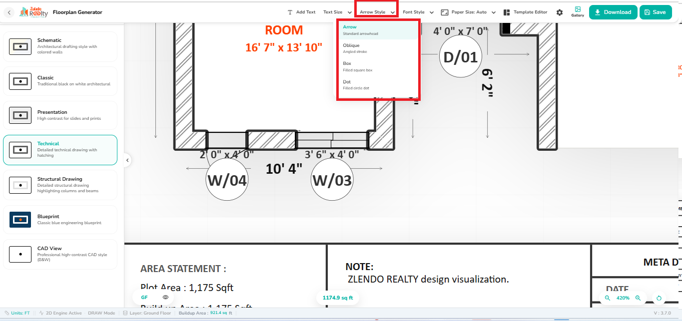
Arrow Style #
Change leader and annotation arrow styles.
Steps #
- Click Arrow Style from the top toolbar.
- Select the preferred arrowhead style from the dropdown menu.
- The selected style is applied to dimension and annotation arrows in the drawing.
- Review the updated floor plan appearance.
- Save or download the drawing after finalizing the arrow style.
- Arrow: Standard arrowhead.
- Oblique: Angled stroke.
- Box: Filled square box.
- Dot: Filled circle dot.
Font Style #
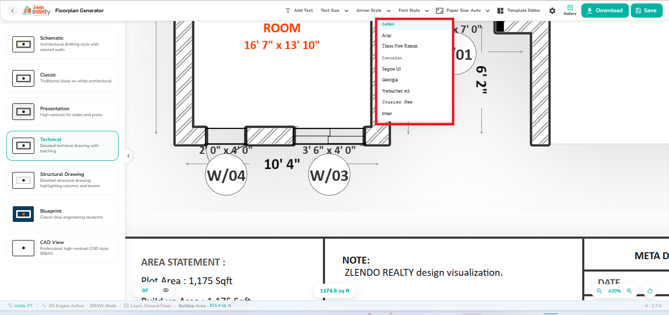
Select different font formats for drawing labels and annotations.
Steps #
- Click Font Style from the top toolbar to open the dropdown menu.
- Select the desired font from the available options.
- The selected font is applied to text labels and annotations in the drawing.
- Review the updated appearance of the floor plan.
- Save or download the drawing after finalizing the font style.
Available fonts
- Calibri
- Arial
- Times New Roman
- Consolas
- Segoe UI
- Georgia
- Trebuchet MS
- Courier New
- Inter
Paper Size #
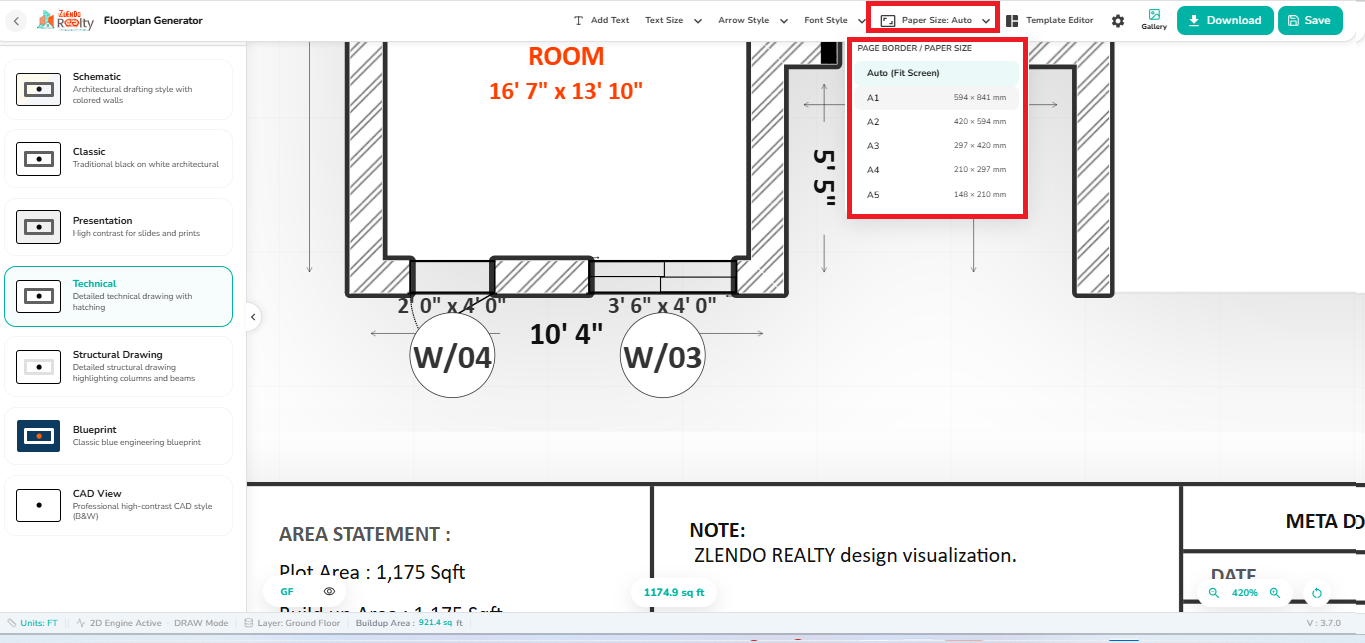
Choose the sheet size for printing and export.
Steps #
- Click Paper Size from the top toolbar.
- Open the Page Border / Paper Size dropdown menu.
- Select the required paper size from Auto or A1 to A5.
- The drawing sheet updates automatically to match the selected paper size.
- Review the layout and adjust annotations if required.
- Save or download the drawing.
- Auto (Fit Screen): Automatically fits the drawing to the available sheet space.
- A1: 594 × 841 mm.
- A2: 420 × 594 mm.
- A3: 297 × 420 mm.
- A4: 210 × 297 mm.
- A5: 148 × 210 mm.
Template Editor #
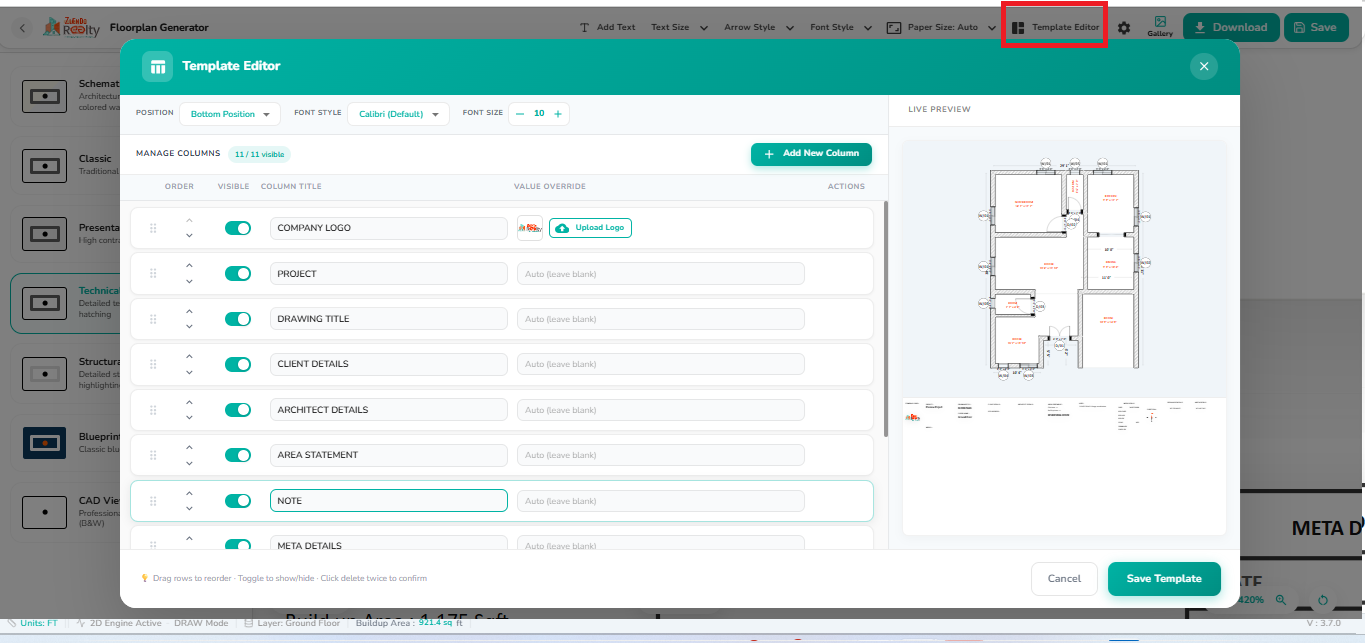
Modify title block and sheet template details.
Steps #
- Click Template Editor from the top toolbar.
- Select the Position for the title block: Top or Bottom.
- Choose the required Font Style and Font Size.
- Enable or disable template fields using the Visible toggle.
- Edit the template sections as required.
- Upload a custom company logo using Upload Logo.
- Drag and reorder fields to customize the title block layout.
- Preview changes in the Live Preview panel.
- Click Save Template to apply the modifications.
Template sections
- Company Logo
- Project
- Drawing Title
- Client Details
- Architect Details
- Area Statement
- Note
- Meta Details
Settings — General Preferences #
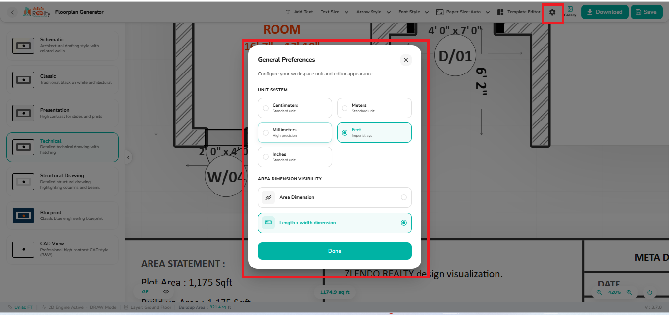
Configure measurement units and dimension display settings.
Steps #
- Click the Settings gear icon from the top toolbar.
- The General Preferences dialog opens.
- Under Unit System, select Centimeters, Meters, Millimeters, Feet, or Inches.
- Under Area Dimension Visibility, choose the dimension display format.
- Click Done to apply the changes.
- Area Dimension: Displays area measurements.
- Length × Width Dimension: Displays room dimensions as length and width.
Gallery #
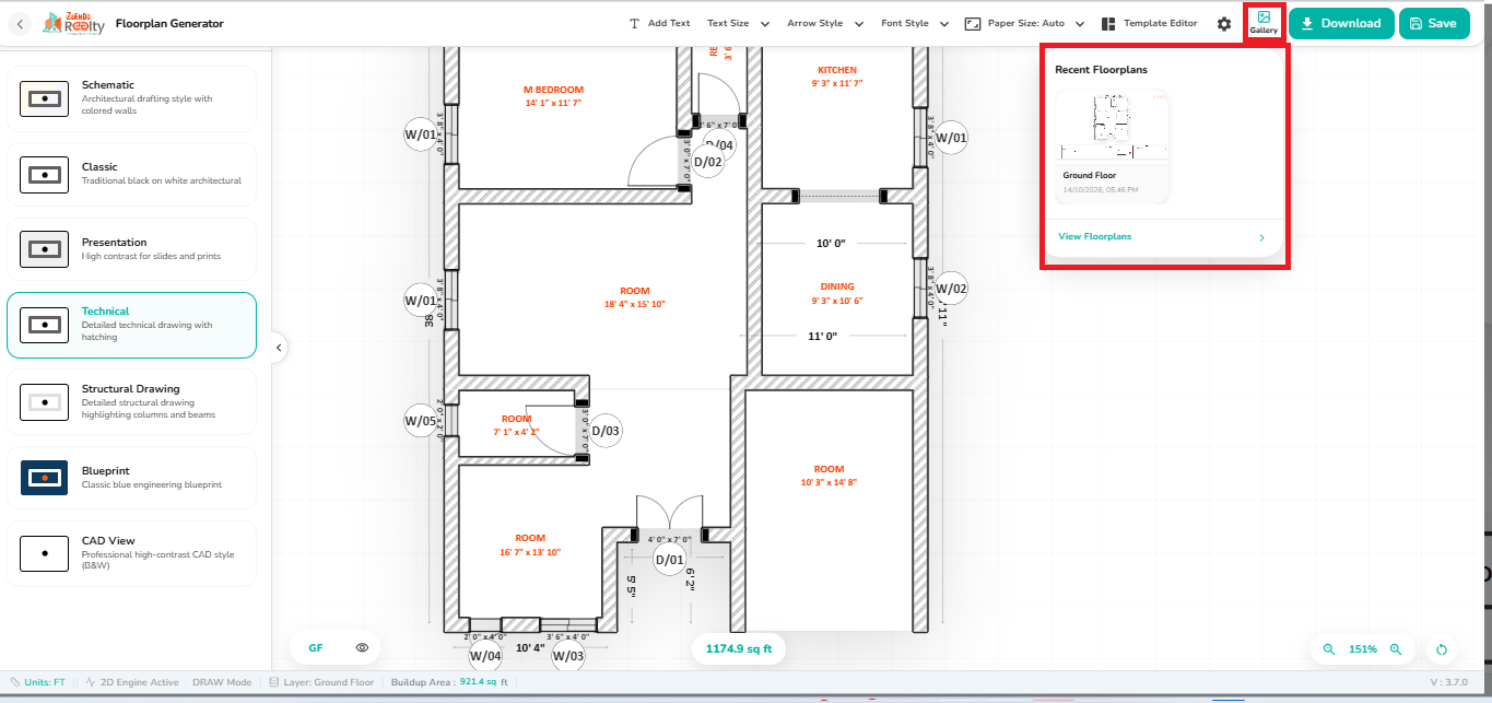
Access saved templates and layouts.
Steps #
- Click Gallery from the top toolbar.
- The Recent Floorplans panel opens on the right side.
- Browse the list of recently accessed floor plan drawings.
- Click a floor plan thumbnail to preview or open it.
- Select View Floorplans to access the complete floor plan gallery.
- Choose the required floor plan for reference, editing, or export.
Download #
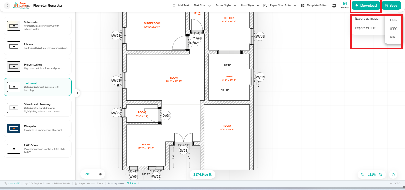
Export the drawing in the selected format.
Steps #
- Click Download from the top toolbar.
- Choose Export as Image (PNG, JPEG, or GIF) or Export as PDF.
- The selected drawing is generated in the chosen format.
- Save the exported file to your local device.
- Share or print the exported floor plan as needed.
Save #
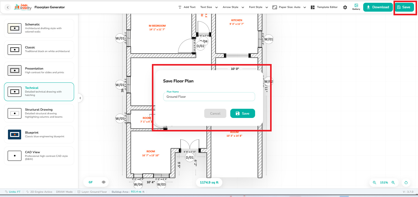
Save the customized drawing layout for future use.
Steps #
- Click Save from the top toolbar.
- The Save Floor Plan dialog opens.
- Enter or modify the Plan Name.
- Review the floor plan name before saving.
- Click Save to store the floor plan.
- The updated drawing and export settings are saved for future access.
4. Floor Selection #
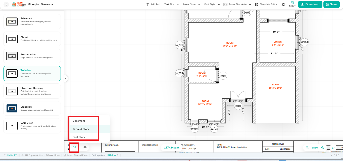
Users can quickly switch between different building levels using the floor selector at the bottom-left corner of the screen. The currently active floor is highlighted, while the dropdown menu displays all available floors in the project.
Selecting a floor updates the drawing area to display the corresponding floor plan, making it easy to review, edit, and export individual levels of a multi-story building.
Steps #
- Click the Floor Selector at the bottom-left corner of the workspace.
- The floor list opens, displaying available levels such as Basement, Ground Floor, and First Floor.
- Select the required floor from the list.
- The drawing view automatically switches to the selected floor plan.
- Continue editing, reviewing, or exporting the selected floor.
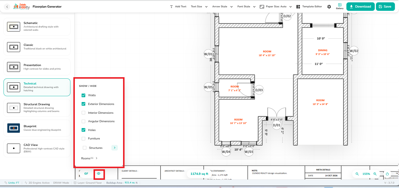
5. Show / Hide Drawing Elements #
This feature allows users to control which drawing elements are displayed in the floor plan.
Users can toggle the visibility of walls, dimensions, furniture, structural components, openings, and room-related information to create cleaner drawings for documentation, presentations, or technical reviews.
Changes are applied immediately, allowing users to customize the floor plan view before saving or exporting.
Steps #
- Click the Visibility (Eye) icon next to the floor selector.
- The Show / Hide panel opens.
- Enable or disable the required drawing elements.
- Expand category options, such as Rooms, to control the visibility of specific elements.
- The drawing updates instantly based on the selected visibility settings.
- Continue reviewing, editing, or exporting the floor plan.
- Walls
- Exterior Dimensions
- Interior Dimensions
- Angular Dimensions
- Holes
- Furniture
- Structures