3D Visualization and 360° Walkthrough #
The 3D Visualization and 360° Walkthrough feature allows users to explore their design in a realistic three-dimensional environment. It provides an immersive view of the building, including walls, roofs, flooring, textures, materials, furniture, and other design elements.
Users can navigate through the project, inspect spaces from different angles, and understand the overall look and feel of the design before construction or rendering.
Switching from 2D Mode to 3D #
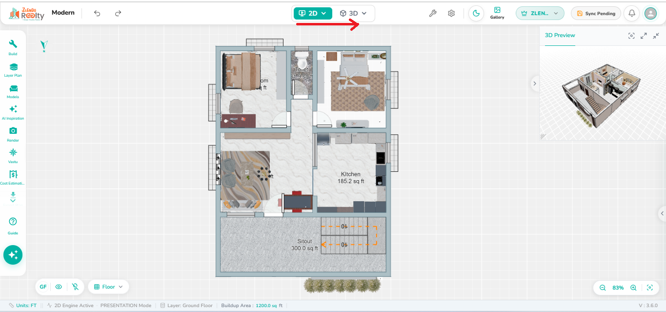
The 2D to 3D Mode Switch enables users to seamlessly transition from a two-dimensional floor plan view to a fully interactive three-dimensional model. While 2D Mode is used for creating and editing architectural elements such as walls, rooms, doors, windows, roofs, and assets, 3D Mode provides a realistic visualization of the complete building design.
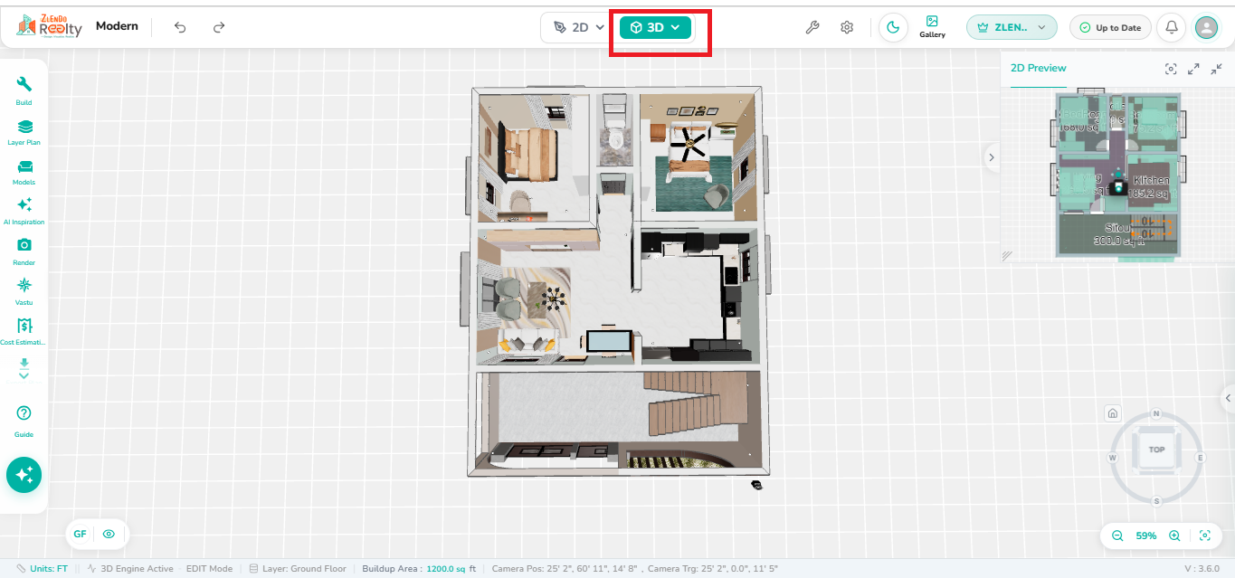
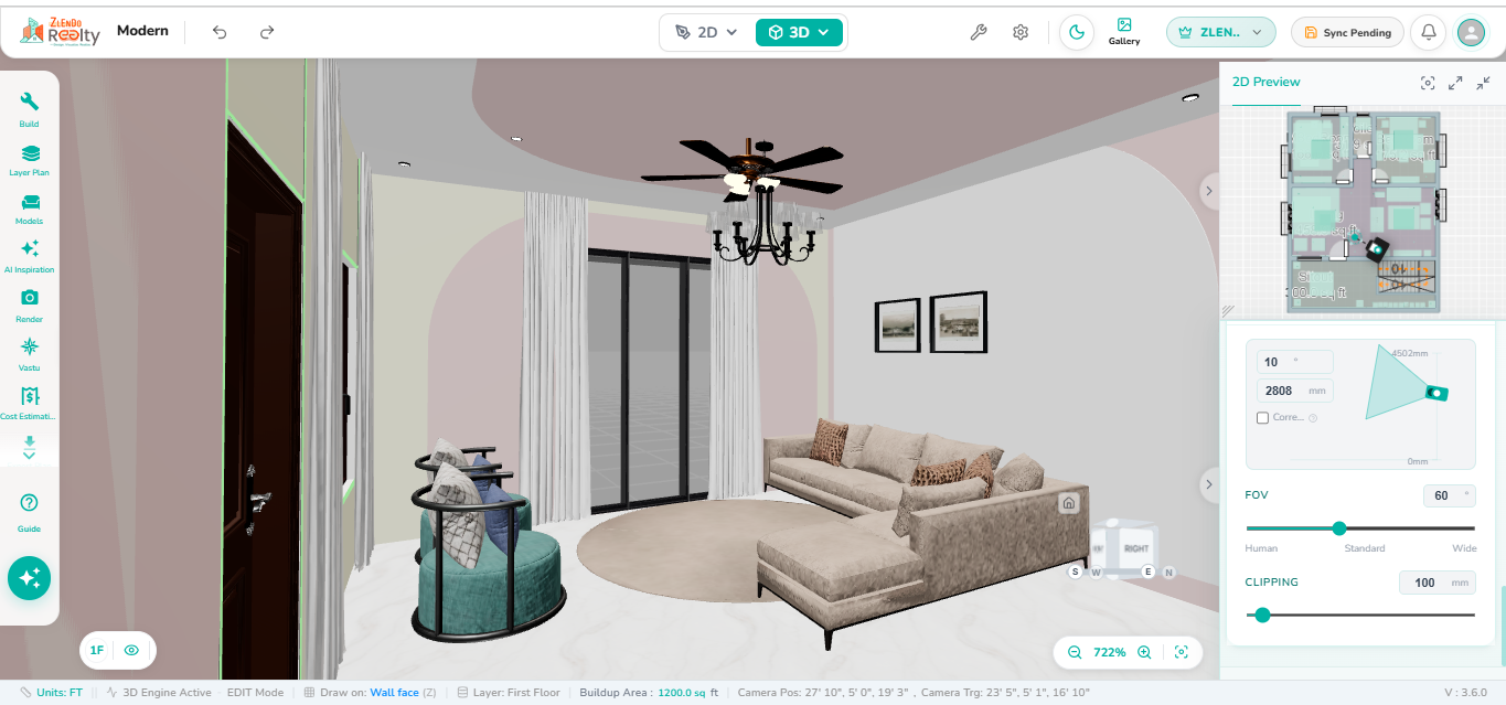
When users switch to 3D Mode, the system automatically generates a three-dimensional representation of the project, including walls, roofs, flooring, textures, materials, furniture, and other placed assets. This allows users to review the design from multiple perspectives and better understand the final appearance of the structure.
The 2D/3D View Switch located in the top toolbar allows users to quickly change between floor plan editing and three-dimensional visualization modes.
Editing in 3D #
Advanced Wall Editing in 3D Mode #
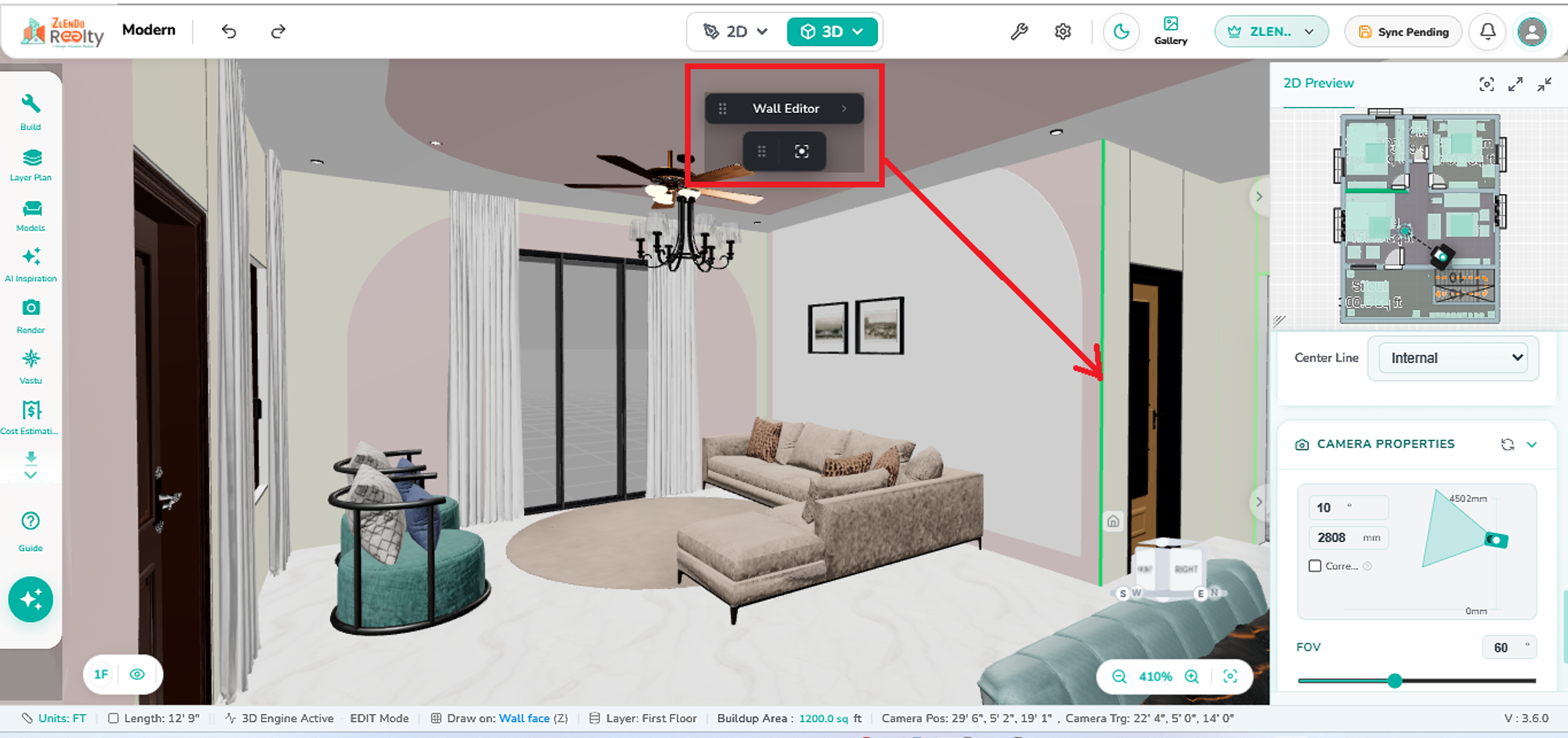
The Advanced Wall Editing in 3D Mode feature enables users to directly modify walls while working in the 3D environment. When a wall is selected, the system highlights the wall and displays a Wall Editor popup toolbar, providing quick access to wall editing functions without switching back to 2D mode.
Wall Editor – Draw and Modification Tools #
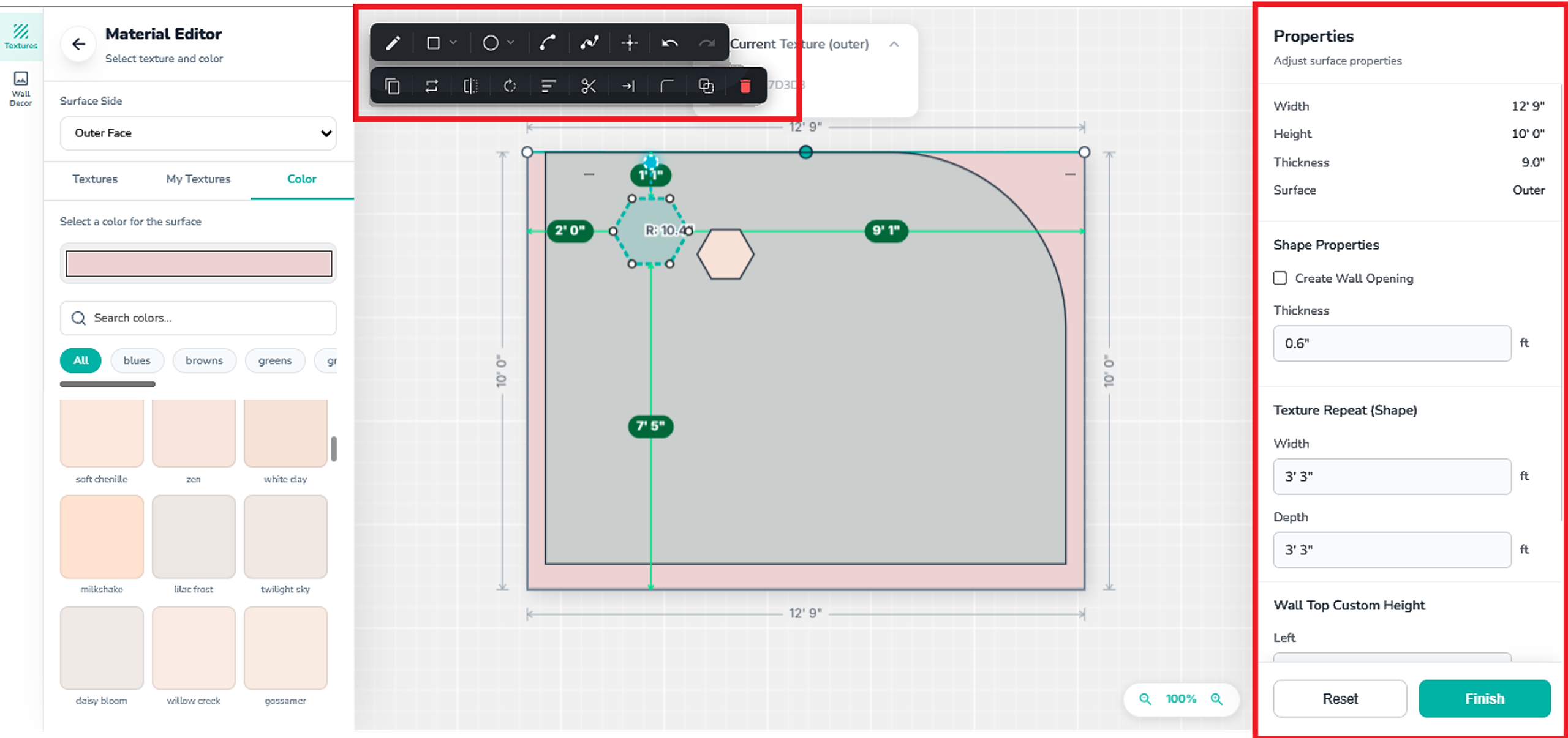
The Wall Editor window opens when users select Wall Editor from a wall in 3D Mode. It provides advanced editing capabilities that allow users to create custom wall designs, modify wall boundaries, apply textures and colors, and adjust wall properties within a dedicated editing workspace.
The editor contains Draw Tools, Modification Tools, Material Editor, and Wall Properties, enabling complete wall customization without returning to the floor plan.
Draw Tools #
Line
Creates straight wall boundary segments for defining custom wall shapes.
Rectangle
Draws rectangular shapes on the wall surface for creating custom patterns and wall features.
Circle
Creates circular shapes that can be used for decorative wall elements or openings.
Arc
Draws curved arc segments for creating rounded wall features and custom decorative shapes.
Polyline
Creates connected line segments that allow users to define complex custom wall geometries.
Reference Point
Provides reference points and guides to assist with accurate shape creation and alignment.
Modification Tools #
Copy
Creates a duplicate of the selected wall shape or design element.
Move
Repositions the selected shape or element to a new location on the wall.
Split
Divides a selected shape or segment into multiple editable sections.
Rotate
Rotates the selected element around a specified point.
Mirror
Creates a reflected copy of the selected shape for symmetrical designs.
Trim
Removes unwanted portions of intersecting shapes or wall elements.
Extend
Extends selected lines or boundaries until they meet another element.
Offset
Creates a parallel copy of the selected shape at a specified distance.
Fillet
Creates smooth rounded corners between intersecting segments.
Align
Aligns selected elements with reference geometry or neighboring objects.
Lock
Prevents accidental modification of selected wall elements.
Delete
Permanently removes the selected shape or wall feature from the wall editor.
Material Editor #
Surface Side
Allows users to select the wall surface to edit, such as Outer Face or Inner Face.
Textures
Applies predefined material textures to the selected wall surface.
My Textures
Provides access to user-uploaded or custom texture libraries.
Color
Applies solid colors to the selected wall surface and decorative features.
Wall Properties #
Width
Displays the width of the selected wall section or wall feature.
Height
Defines the vertical height of the wall.
Thickness
Controls the depth of the wall structure.
Surface
Indicates the currently selected wall face being edited.
Create Wall Opening
Creates custom openings within the wall surface.
Texture Repeat (Width & Depth)
Controls how textures are repeated and tiled across the wall surface.
Wall Top Custom Height
Allows customized wall top profiles and varying wall heights for advanced wall designs.
Finish
Applies and saves all changes made within the Wall Editor.
Reset
Reverts unsaved changes and restores the previous wall configuration.
Real-Time Wall Shape Updates in 3D View #
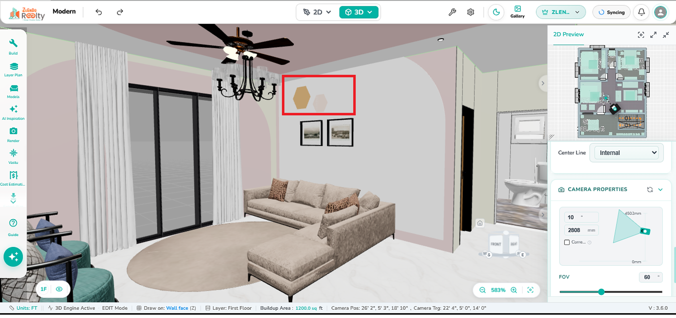
The Real-Time Wall Shape Updates in 3D View feature enables users to instantly visualize custom wall designs created in the Wall Editor. Any shapes, patterns, openings, decorative elements, textures, or surface modifications added within the editor are automatically reflected on the wall in the 3D environment.
This live update functionality allows users to review wall customizations immediately without leaving the 3D workspace. As shapes are drawn or modified in the Wall Editor, the changes are applied directly to the selected wall, providing an accurate preview of the final design.
Move Selected Asset in 3D Mode #
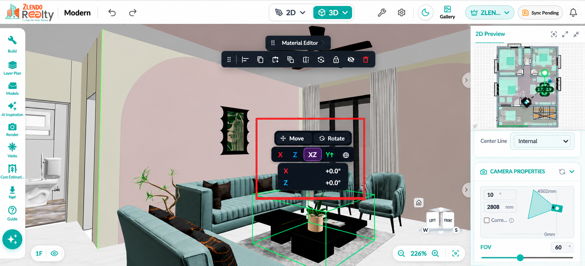
The Move Asset feature allows users to reposition selected furniture, décor, and other assets directly within the 3D environment. When an asset is selected, a Move control panel appears, enabling precise placement using directional axes and coordinate values.
The selected asset is highlighted with a bounding box, making it easy to identify and adjust its location within the room. Users can move the asset along the X, Y, and Z axes to achieve the desired placement while viewing the changes in real time.
Axis Controls (Move Tool) #
When the Move tool is activated, you can reposition the selected asset using the movement axes displayed around the object.
X Axis (Left ↔ Right) #
Moves the selected asset horizontally from left to right within the room.
Y Axis (Up ↕ Down) #
Moves the selected asset vertically in the floor plan direction, from up to down.
XZ Axis (Diagonal Movement) #
Allows the selected asset to move diagonally by combining movement across multiple directions simultaneously. This enables faster positioning without adjusting each axis separately.
Rotate Selected Asset in 3D Mode #
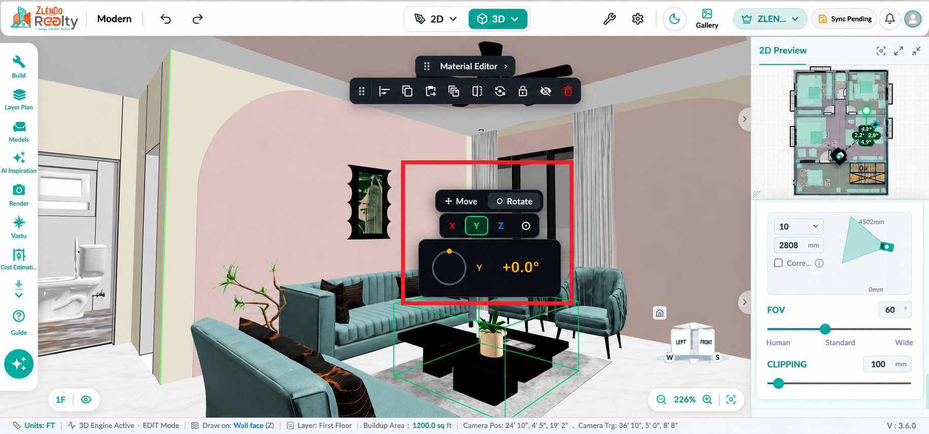
The Rotate tool allows users to adjust the orientation of a selected asset directly within the 3D environment. When an asset is selected and the Rotate option is activated, rotation controls appear for the X, Y, and Z axes. Users can precisely rotate the asset by entering angle values or using the rotation control.
Rotation Axes #
X Axis (Pitch) #
Rotates the asset forward and backward around the X-axis.
Y Axis (Yaw) #
Rotates the asset left and right around the vertical axis.
Z Axis (Roll) #
Rotates the asset sideways around the Z-axis.
Show All Floors View in 3D #
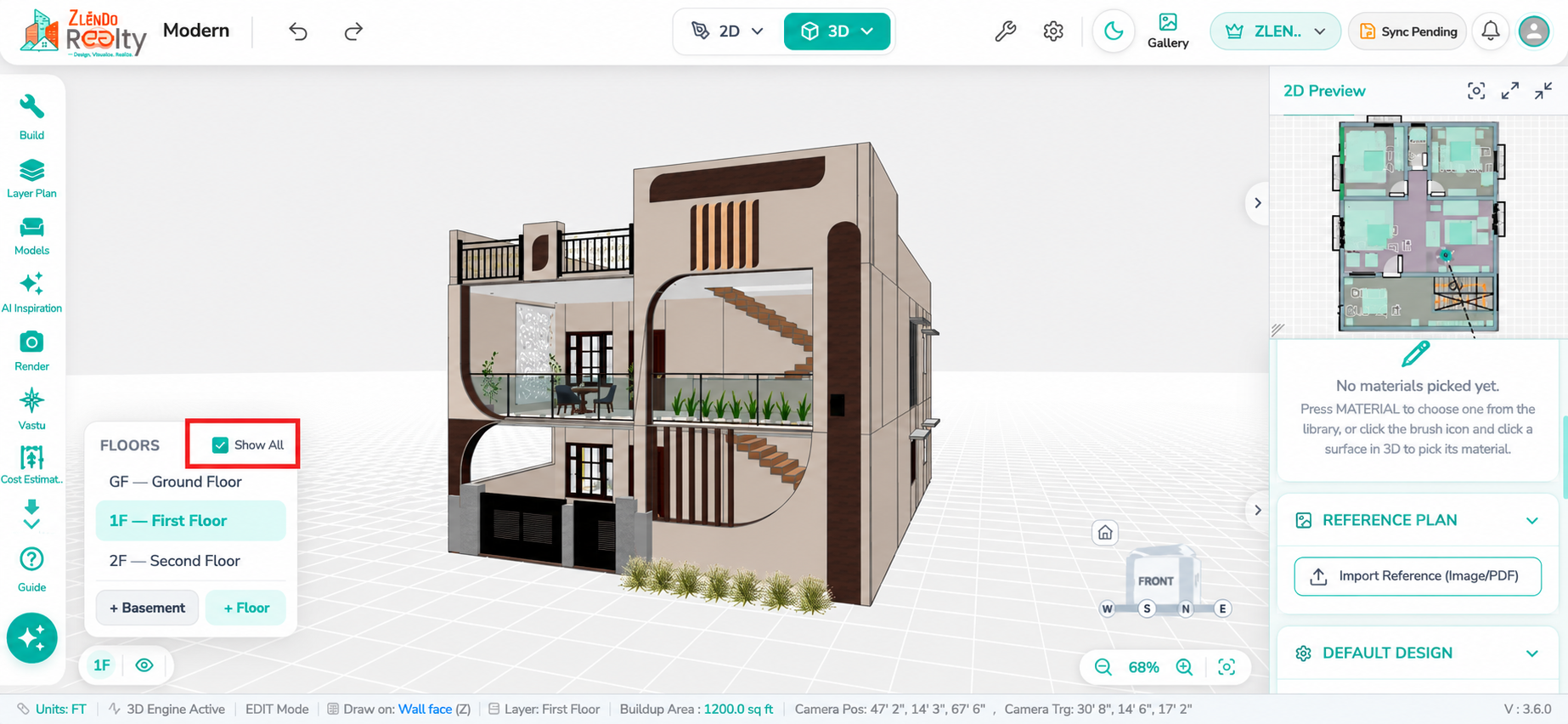
The Show All checkbox allows you to display all building floors simultaneously in the 3D view. When enabled, every floor in the project becomes visible together, making it easier to review the overall structure, floor alignment, stair connectivity, and multi-level design relationships. When disabled, only the currently selected floor is displayed for focused editing.
Color Picker and Material Selection Tool #
Color Picker #
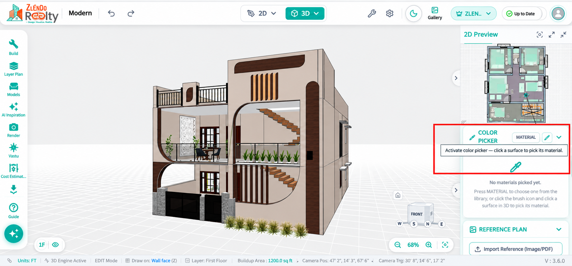
The Color Picker tool allows you to quickly copy an applied color, texture, or material from one surface and apply it to other surfaces in the project.
To use this feature, select Color Picker from the right-side properties panel and click on the surface containing the desired material. Once a material is picked, the cursor changes to a brush icon, indicating that the selected color or texture is ready to be applied. You can then click on any compatible surface to paste the material.
The Color Picker remains active, allowing you to continuously apply the selected material to multiple surfaces without needing to pick it again. To paste the same material on another floor, simply switch to the required floor layer and continue applying the material wherever needed.
Material Selection and Paint Tool #
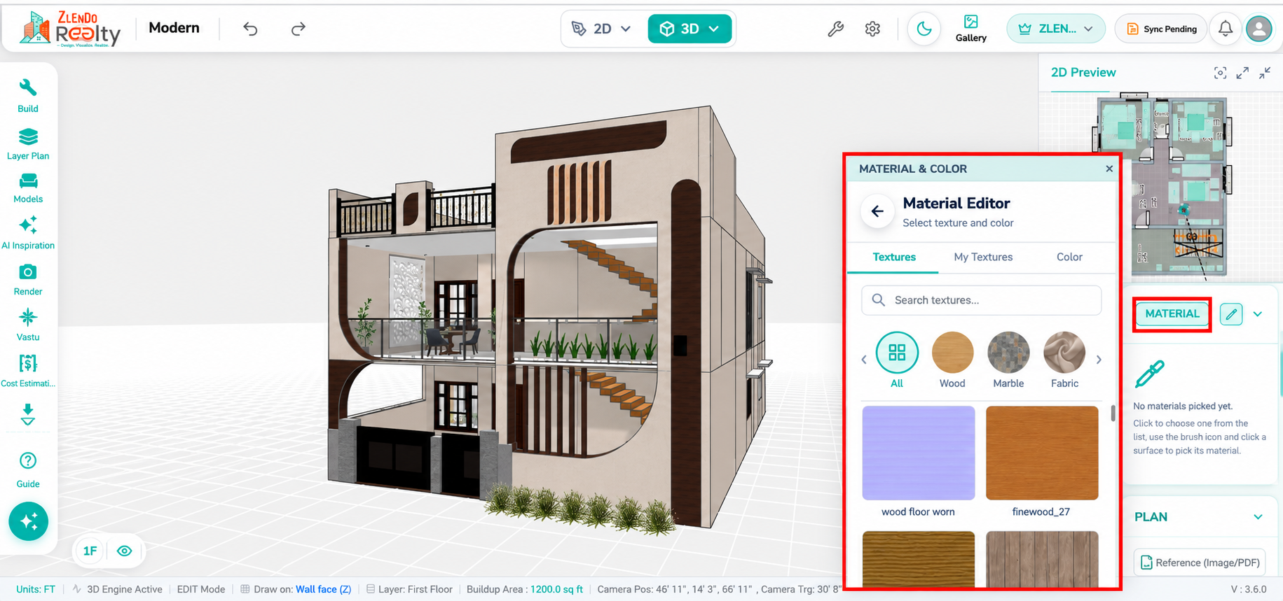
The Material option allows you to select and apply colors or textures directly to surfaces in the 3D model. Click the Material button in the properties panel to open the Material Editor, where you can browse and choose from available textures, custom materials, or solid colors.
Once a material or color is selected, the cursor changes to a brush icon, indicating that the selected material is ready for application. Simply click on any compatible surface in the 3D view to apply the chosen material.
The selected material remains active, allowing you to continuously paint multiple surfaces without reopening the Material Editor. To apply the same material on a different floor, switch to the desired floor layer and continue painting surfaces as needed.
Reference Image Upload in 3D/2D #
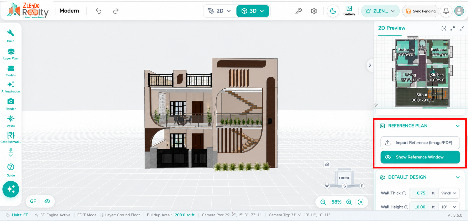
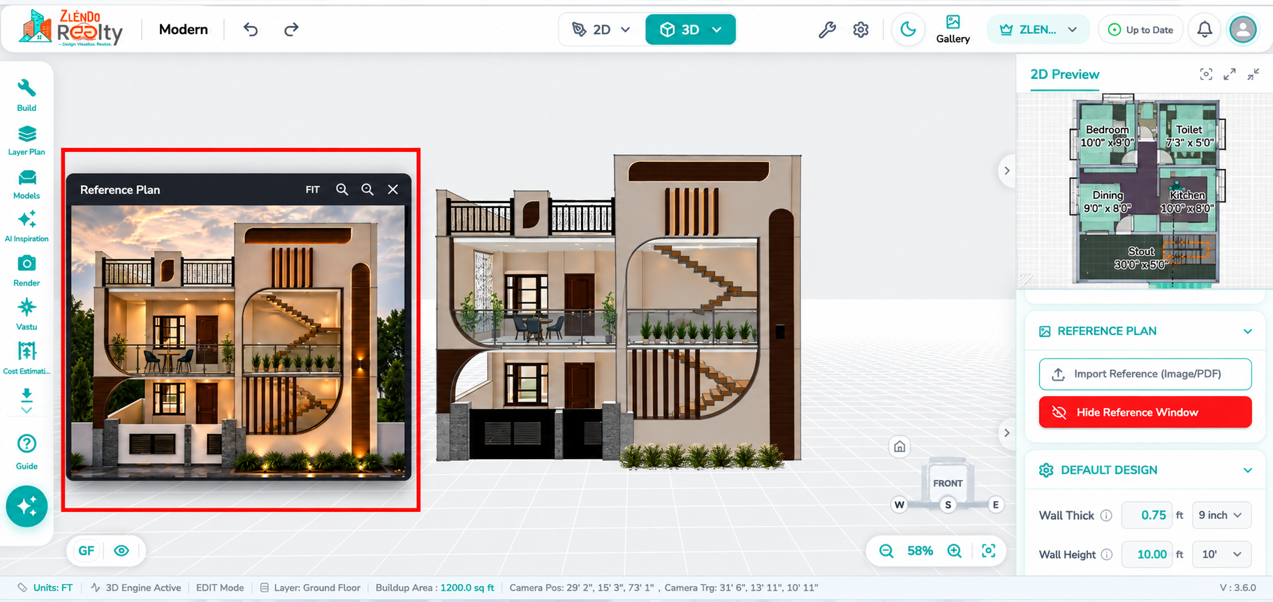
The Reference Image Upload option allows you to import an image or PDF and use it as a visual guide while designing in both 2D and 3D views. This is useful for matching elevations, floor plans, concept sketches, façade designs, or any external reference during the modeling process.
Once a reference image is loaded, it opens in a separate Reference Viewer window. You can:
- Move the reference window anywhere within the workspace.
- Zoom In to examine fine details more closely.
- Zoom Out for a broader view of the reference.
- Use Fit to automatically adjust the image within the viewer window.
- Keep the reference visible while working on your design in real time.
- Use the reference in both 2D and 3D modes without interrupting your workflow.
When the reference is no longer needed, you can click Hide Reference Window to remove it from the workspace. The reference can be displayed again at any time using the Show Reference Window option.
Camera Position and Perspective Controls #
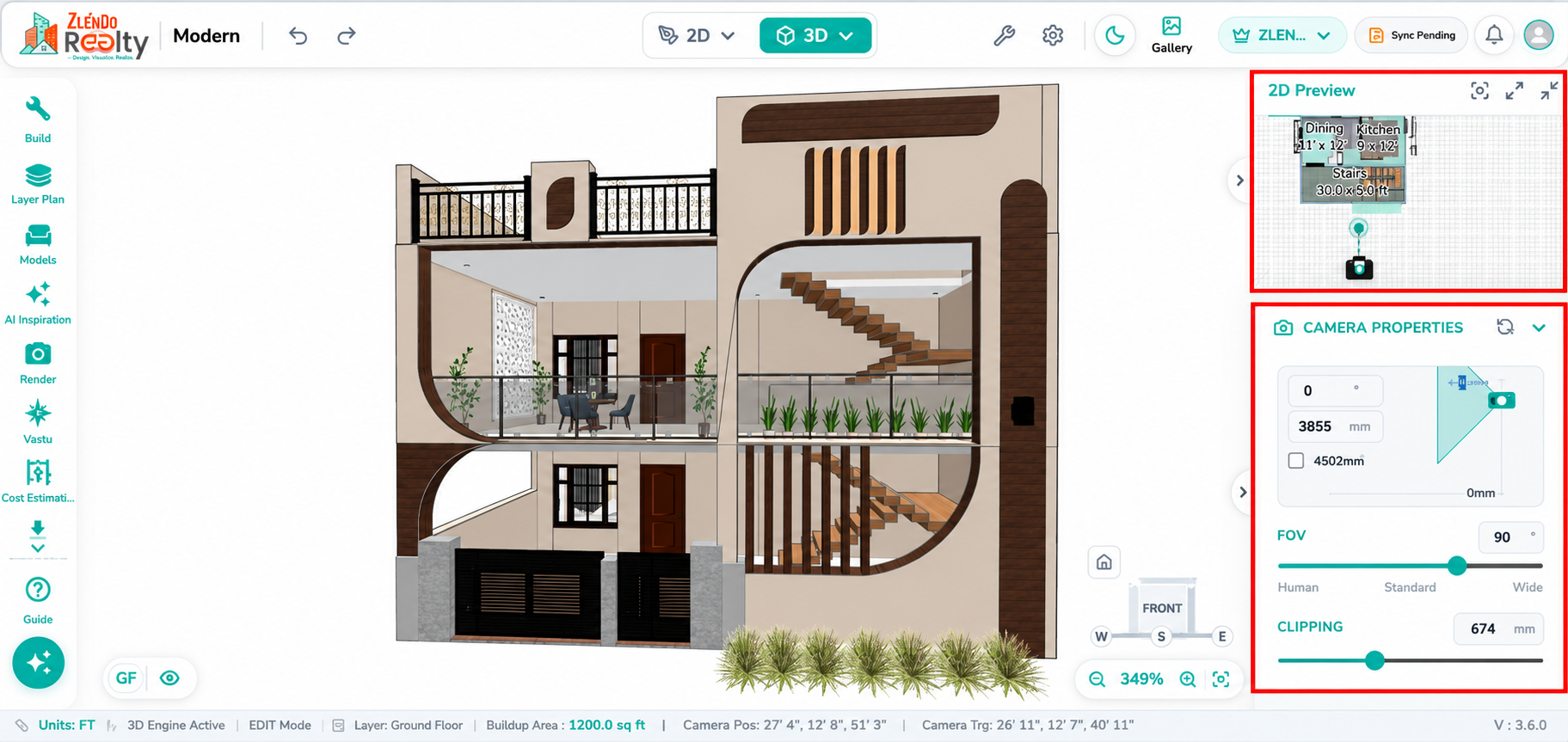
The 2D Preview panel provides an easy way to control and visualize the camera position within your project. By dragging the camera icon, you can quickly set the camera location, while rotating the camera direction allows you to define the viewing angle for the 3D workspace.
Any changes made in the 2D Preview are reflected instantly in the 3D view.
The 2D Preview also includes additional viewing controls:
- Fit to View – Automatically adjusts the preview to display the entire floor plan within the preview window.
- Full Screen – Expands the 2D Preview panel for a larger and more detailed view of the floor plan and camera position.
- Collapse Panel – Minimizes the 2D Preview panel to create more workspace while modeling.
For precise viewpoint adjustments, the Camera Properties panel allows you to configure:
- Camera Height – Sets the elevation of the camera from the ground level.
- FOV (Field of View) – Controls the width of the camera view, from narrow to wide-angle perspectives.
- Clipping Distance – Defines the visible depth range of the camera, helping focus on specific areas or create sectional views.
- Reset Camera Settings – Restores the camera properties to their default values, allowing you to quickly return to the standard viewing configuration.
Together, the 2D Preview and Camera Properties tools provide quick and precise control over camera placement, orientation, and viewing settings for design reviews, walkthroughs, screenshots, and rendering.
View Cube Navigation #
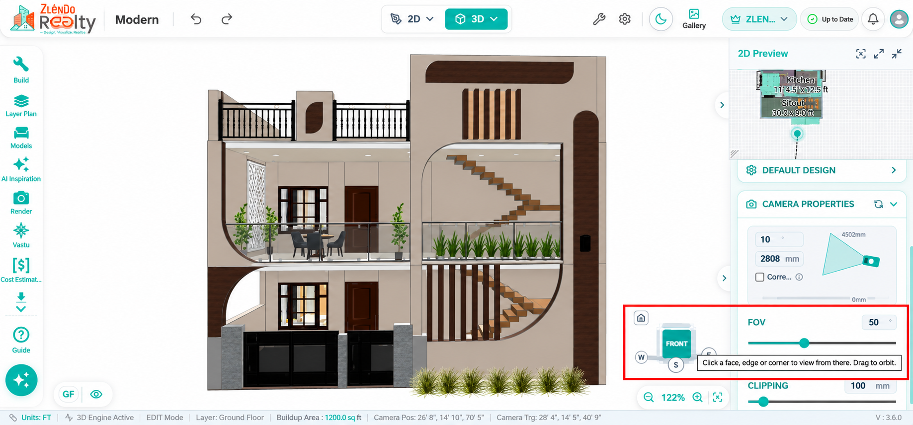
The View Cube provides a quick and intuitive way to change the viewing orientation of your 3D model. Located in the 3D workspace, the cube displays the current view direction and allows you to instantly switch between standard views.
You can:
- Click a face of the cube to switch to a predefined view such as Front, Back, Left, Right, Top, or Bottom.
- Click an edge or corner to view the model from angled or isometric perspectives.
- Drag the View Cube to freely orbit and rotate around the model.
- Quickly align the camera to common architectural viewpoints for easier navigation and design review.
- Use the Home button above the cube to return to the default view orientation.
The View Cube makes it easy to inspect the model from different angles without manually rotating the camera.
3D CAD Elevation Editor #
The CAD Tool allows you to create and edit custom elevation elements directly in the 3D Top View. This feature is useful for designing façade details, decorative frames, projections, grooves, custom shapes, and elevation features with precise control.
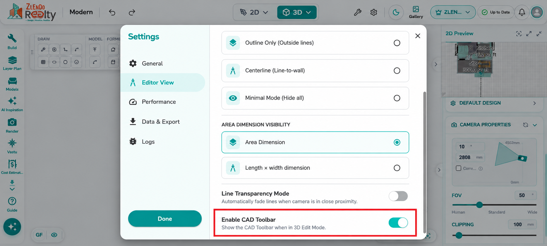
Before using the CAD Tool, enable CAD Toolbar from Settings → Editor View → Enable CAD Toolbar. Once enabled, switch to 3D Top View to access the CAD editing tools.
The CAD Toolbar includes the following categories:
Draw #
Create 2D CAD profiles and shapes.
- Line
- Rectangle
- Polygon
- Circle
- Arc
- Spline
- Reference Line
- Additional shape creation tools
Model #
Create and manage editable CAD profiles used for elevation design.
Forms #
Convert shapes into different forms and profile variations.
Build As #
Defines how the selected shape is generated:
- Solid – Creates a solid 3D element. Shortcut Key P for Push/Pull
- Void – Creates a cutout or opening from a solid object. Shortcut Key Push/Pull
Transform #
Modify the position and orientation of CAD objects:
- Move
- Rotate
- Position adjustments
- Other transformation operations
Modify #
Edit existing CAD shapes:
- Trim
- Extend
- Mirror
- Offset
- Join and split operations
- Additional shape modification tools
Measure #
Measure distances and dimensions within the CAD workspace.
Guides #
Create temporary guides and construction references to assist accurate modeling.
CAD Shape Properties Panel #
When a CAD object is selected, its properties appear in the CAD Shape Properties panel.
Name: Displays or edits the name of the selected CAD object.
Structure: Defines how the shape is generated. Example: 3D Solid Extrusion
Profile: Shows the profile type used to create the object. Example: Rectangle (5 Pts)
Elevation: Adjusts the vertical position of the CAD object relative to its placement level.
Height: Controls the extrusion height of the selected shape.
Width: Adjusts the width of the selected profile.
Depth: Controls the depth or projection of the CAD object.
Texture Repeat: Controls how applied textures are repeated across the selected surface.
Delete: Removes the selected CAD object from the model.
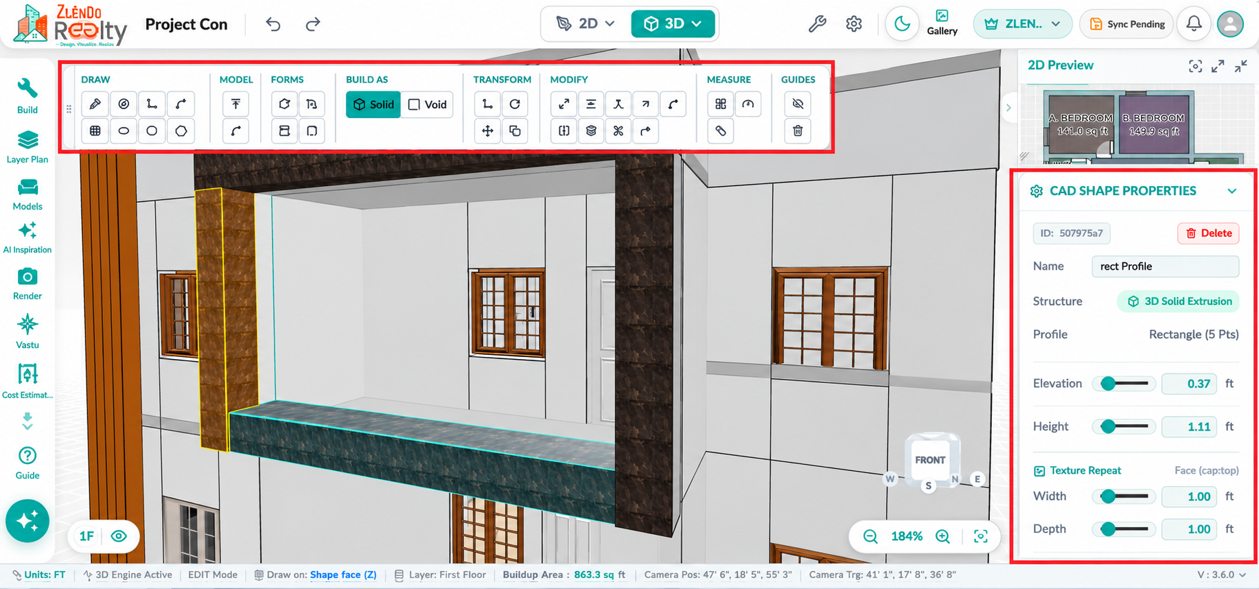
Example: Creating an Elevation Projection Using Rectangle and Push/Pull #
Step 1: Enable the CAD Toolbar #
- Open Settings.
- Navigate to Editor View.
- Enable the CAD Toolbar option.
- Click Done to save the settings.
Step 2: 3D Edit Mode #
- Open the project in 3D View.
- Switch to a suitable Top View or elevation editing view.
- Ensure the wall surface where the elevation feature will be created is visible.
Step 3: Draw a Rectangle #
- In the CAD Toolbar, select Draw → Rectangle.
- Click on the wall surface to define the starting point.
- Move the cursor to set the required size.
- Click again to complete the rectangular profile.
- Enter the desired dimensions if required and click Apply.
Step 4: Create a Projection Using Push/Pull #
- Select the newly created rectangular shape.
- Click the Push/Pull tool from the CAD toolbar.
- Drag the selected shape outward from the wall to create a projection.
- Enter a precise extrusion depth if required.
- Click to complete the operation.
Step 5: Adjust Shape Properties #
- Select the projected CAD shape.
- Open the CAD Shape Properties panel.
- Modify the following properties as needed:
- Elevation – Vertical position of the shape.
- Height – Extrusion height.
- Width – Width of the profile.
- Depth – Projection depth.
- Texture Repeat – Material repetition settings.
Step 6: Apply Materials #
- Select the projected elevation element.
- Choose a color or texture from the Material Editor.
- Apply the material to achieve the desired façade appearance.
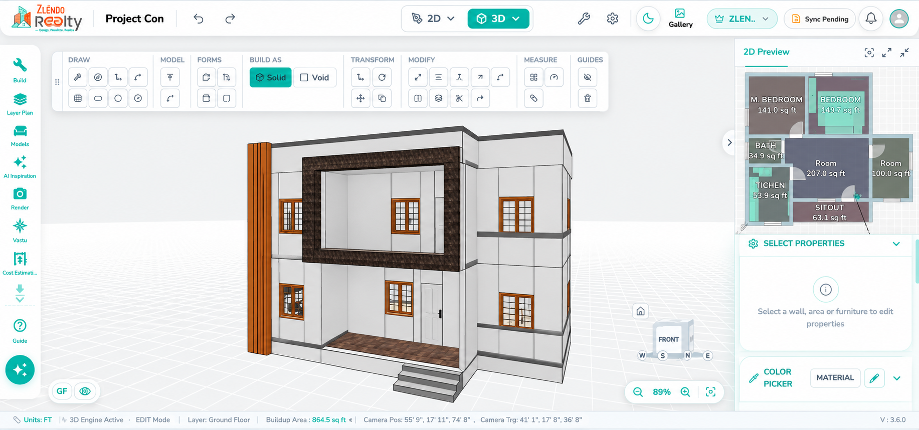
Result #
The rectangular profile is converted into a 3D elevation projection, creating a decorative architectural feature on the building façade. This method can be used to design window frames, balcony borders, feature walls, decorative bands, and other custom elevation elements.
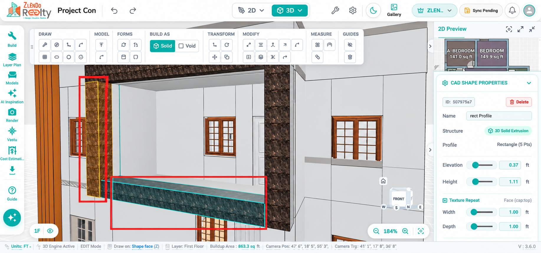
Note: Selecting CAD Surfaces #
When working with CAD shapes in the 3D CAD Elevation Editor, the surface selection state is indicated by different highlight colors:
Note: When the cursor hovers over a CAD surface or rectangular profile, the surface is highlighted blue, indicating that it is available for selection. Once the surface is selected, the highlight changes to orange, confirming that the shape is actively selected and ready for editing.
After the surface is highlighted in orange, you can perform various CAD operations, including:
- Push/Pull – Create projections or recesses.
- Offset – Generate parallel profiles at a specified distance.
- Move – Reposition the selected shape.
- Rotate – Change the orientation of the shape.
- Scale – Adjust the shape size.
- Trim and Extend – Modify profile boundaries.
- Mirror – Create symmetrical copies.
- Delete – Remove the selected CAD element.
- Other available Transform and Modify operations.
This visual feedback helps ensure that edits are applied to the correct CAD surface before performing any modeling operation.
3D Walk Mode #
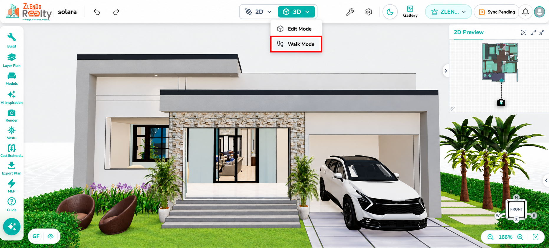
3D Walk Mode allows users to experience a virtual walkthrough of the designed home from a real-world perspective.
To start the walkthrough, switch to 3D View and select Walk Mode from the 3D mode dropdown menu. Users can then move through rooms, hallways, and outdoor areas as if physically walking inside the property.
This mode helps visualize room layouts, furniture placement, space flow, and overall design before construction.
How to Use #
- Open the model in 3D View.
- Click the 3D mode dropdown at the top toolbar.
- Select Walk Mode.
- Navigate through the home using mouse and keyboard controls.
- Explore interior and exterior spaces from a first-person perspective.
Note: Walk Mode provides an immersive home tour experience, making it easier to evaluate accessibility, room connectivity, and design aesthetics from the occupant’s viewpoint.
360° Realistic Walkthrough #
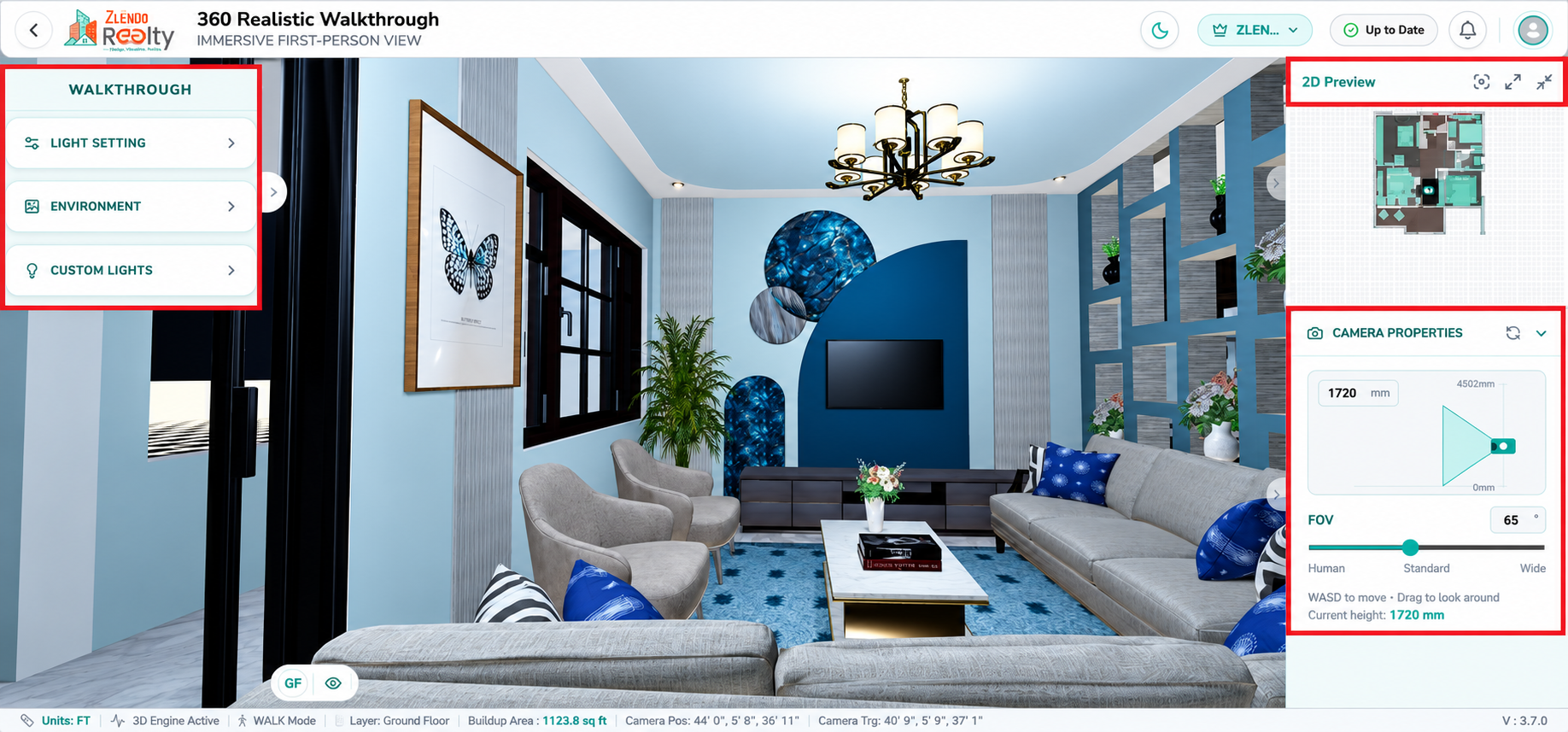
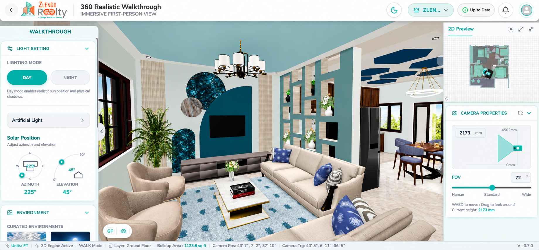
When 3D Walk Mode is selected from the 3D menu, the system launches the 360° Realistic Walkthrough experience.
This mode provides an immersive first-person view, allowing users to virtually walk through and explore the home as if they were physically inside the space.
The walkthrough environment includes several tools to control navigation, visualization, and lighting for a realistic viewing experience.
Available Panels and Tools #
1. 2D Preview #
Displays the floor plan and current camera position in real time. Users can easily understand their location within the project while navigating through the walkthrough.
2. Camera Properties #
Provides controls to adjust:
- Camera Height
- Field of View (FOV)
- Viewing Angle
- Camera Position
These settings help customize the walkthrough perspective for a more natural viewing experience.
3. Light Settings #
The Light Settings panel allows users to simulate realistic lighting conditions within the 360° Realistic Walkthrough.
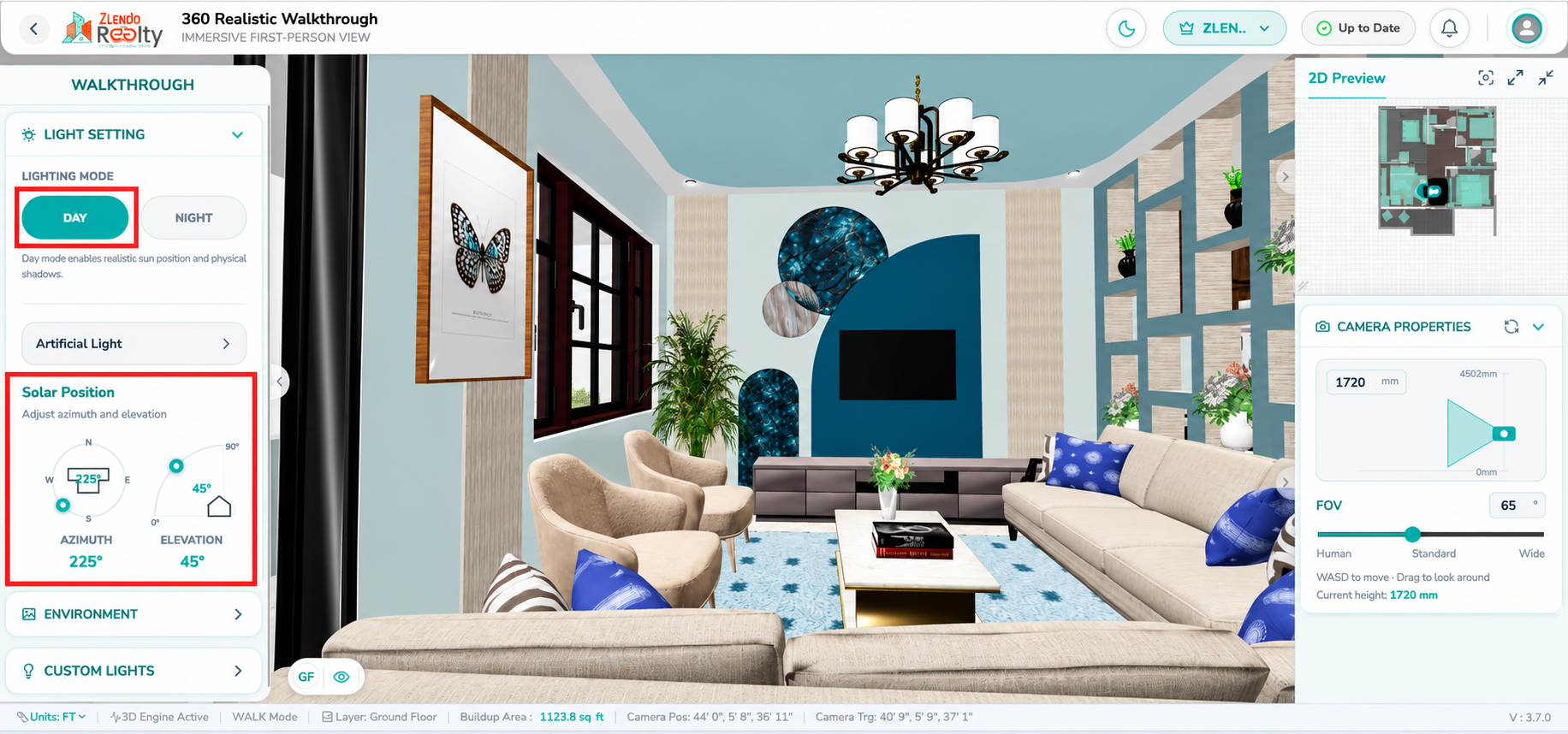
Users can switch between Day Mode and Night Mode to visualize the project under natural sunlight or artificial lighting conditions. The panel also provides controls for adjusting solar position and individual room lighting settings to achieve the desired atmosphere and realism.
Features Available #
Day Mode #
Day Mode simulates natural sunlight and physical shadows throughout the project.
- Enables realistic daylight visualization.
- Displays accurate sun direction and shadow effects.
- Useful for evaluating natural light penetration into rooms.
Solar Position #
Solar Position controls allow users to adjust the sun’s location in the sky.
- Azimuth: Controls the horizontal direction of the sun.
- Elevation: Controls the sun’s height above the horizon.
- Real-time updates help analyze daylight and shadow behavior at different times of the day.
Night Mode #
Night Mode disables daylight and activates artificial lighting within the project.
- Simulates evening and nighttime conditions.
- Helps evaluate interior lighting design and ambience.
- Useful for checking fixture placement and illumination coverage.
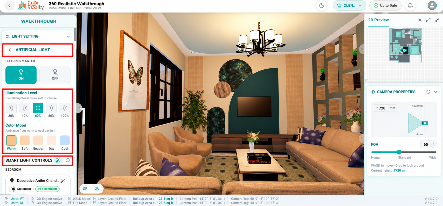
Artificial Light #
Controls the overall operation of lighting fixtures within the walkthrough.
- Turn all fixtures ON or OFF.
- Adjust the overall illumination level of the selected space.
- Preview lighting changes instantly in the walkthrough scene.
Smart Light Controls #
Smart Light Controls provide room-specific lighting customization.
- Automatically detects lights available in the selected room.
- Allows adjustment of Light Intensity for individual fixtures.
- Allows adjustment of Color Temperature from warm to cool lighting.
- Enables realistic lighting customization for each light source independently.
- Helps create different moods such as warm living spaces, neutral workspaces, or bright task lighting.
How to Use #
- Open 360° Realistic Walkthrough.
- Expand Light Settings from the Walkthrough panel.
- Select Day or Night mode.
- For daytime visualization, adjust the Solar Position using Azimuth and Elevation controls.
- For nighttime visualization, enable Artificial Light.
- Open Smart Light Controls and select a room fixture.
- Adjust the fixture’s Intensity and Color Temperature as required.
- Review the lighting changes instantly within the walkthrough.
Note: Day Mode is best suited for analyzing natural lighting and shadow patterns, while Night Mode combined with Smart Light Controls provides precise control over artificial lighting, helping users create realistic interior lighting scenarios and evaluate the overall ambience of each room.
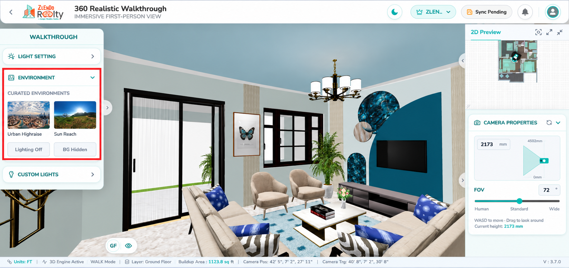
4. Environment Settings #
The Environment Settings panel allows users to enhance the 360° Realistic Walkthrough by applying predefined outdoor surroundings and background scenes.
These curated environments help place the project in different real-world contexts, improving visual realism and providing a better understanding of how the design appears in various locations and atmospheric conditions.
Features Available #
Curated Environments #
Select from a collection of predefined surroundings, such as:
- Urban Highrise – Places the project within a modern cityscape environment.
- Sun Beach – Surrounds the project with a coastal beach setting.
Lighting Control #
- Enable or disable environment-based lighting.
- Adjust how the selected environment influences the overall scene illumination.
Background Visibility #
- Show or hide the environment background.
- Focus solely on the building model when background distractions are not required.
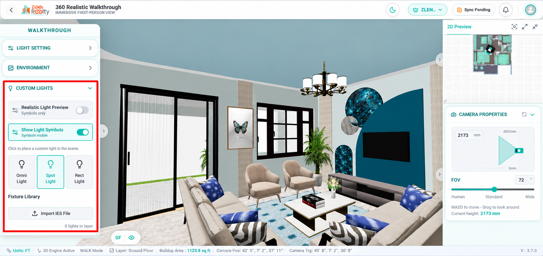
5. Custom Lights #
The Custom Lights panel allows users to add and manage additional light sources within the 360° Realistic Walkthrough.
This feature is useful for enhancing interior and exterior lighting, testing different illumination setups, and creating realistic lighting effects beyond the default fixtures available in the design.
Features Available #
Realistic Light Preview #
- Enables or disables real-time light effect visualization.
- Displays how custom lights influence the scene’s illumination and shadows.
Show Light Symbols #
- Toggles the visibility of light placement symbols in the walkthrough.
- Helps identify and manage custom light locations within the project.
Custom Light Types #
Users can place different types of lighting fixtures:
- Omni Light – Emits light uniformly in all directions from a single point source.
- Spot Light – Projects focused light in a specific direction, ideal for accent and task lighting.
- Rectangular Light – Emits light from a rectangular surface, suitable for large-area and soft lighting effects.
Fixture Library #
- Supports importing custom IES lighting files.
- Allows simulation of manufacturer-specific lighting behavior for more accurate lighting analysis and visualization.
Steps to Access Walk Mode #
- Open the project in 3D View.
- Click the 3D dropdown from the top toolbar.
- Select Walk Mode.
- The system launches the 360° Realistic Walkthrough interface.
- Use the W, A, S, D keys and mouse controls to move and look around the project.
- Refer to the 2D Preview panel to track the current walkthrough location.
- Adjust the walkthrough experience using:
- Camera Properties
- Light Settings
- Environment Settings
- Custom Lights
- Explore the interior and exterior spaces from a realistic first-person perspective.
Note: The 360° Realistic Walkthrough provides a highly immersive way to review the design, evaluate room layouts, assess lighting conditions, and experience the overall look and feel of the home before construction.


