2.0 Version: MEP and Structural #
MEP Tools #
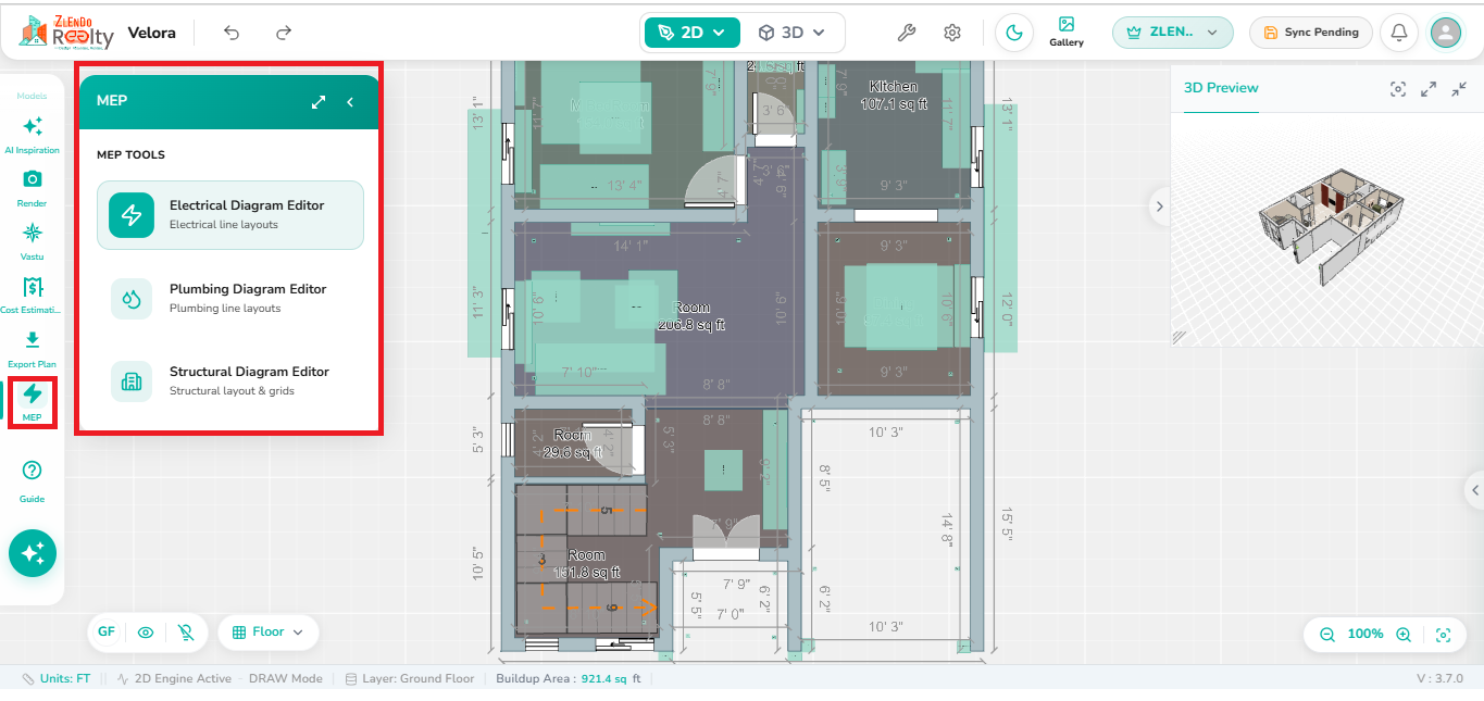
The MEP Tools module provides dedicated editors for designing and managing Electrical, Plumbing, and Structural systems within the building plan.
These tools help create discipline-specific layouts directly on the floor plan, enabling accurate coordination between building services and structural components.
1. Electrical Diagram Editor #
The Electrical Line Diagram Editor enables you to create and manage electrical layouts by placing electrical components, connecting them with wires, and configuring their properties.
The editor provides a symbol library, editing tools, legend display, and customization options to create detailed electrical plans.
Electrical Diagram Panel #
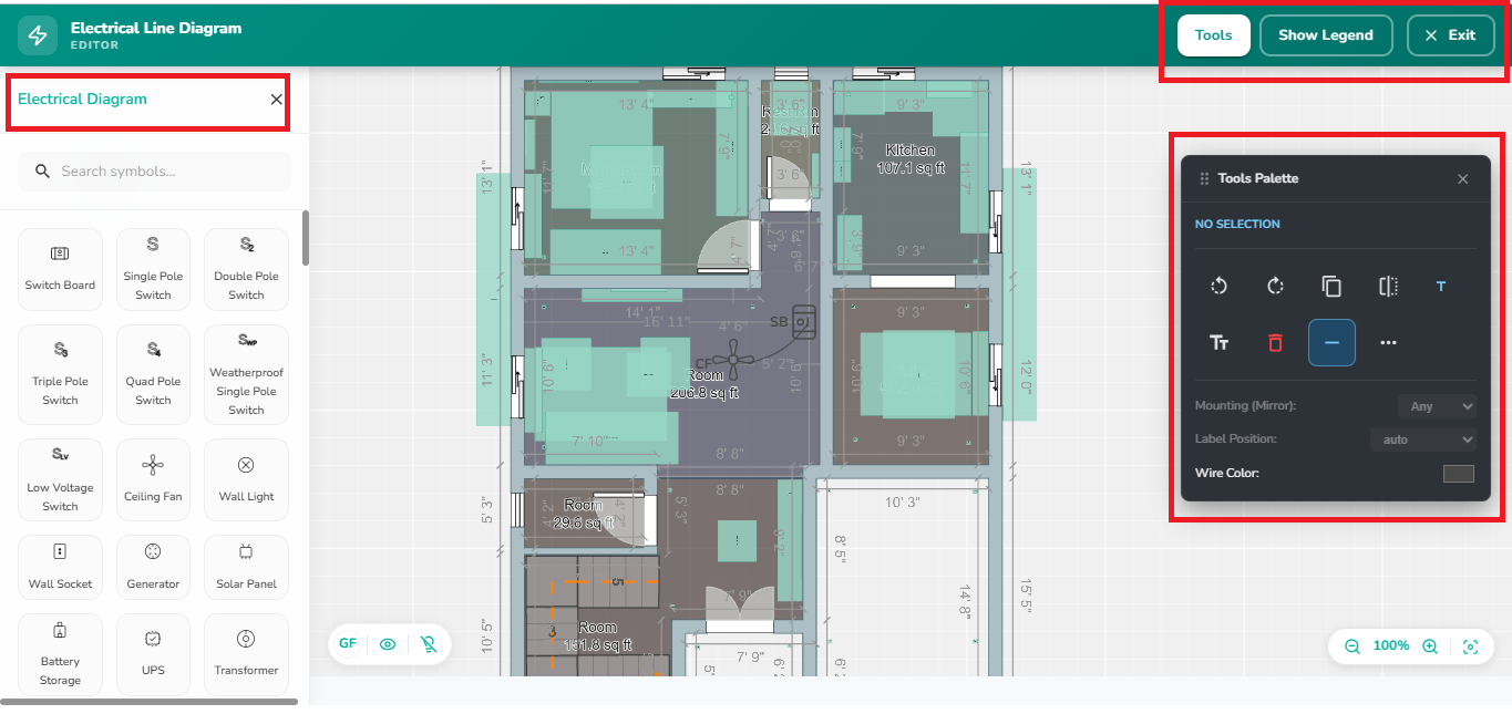
The Electrical Diagram Panel contains electrical symbols and components required for creating electrical layouts.
Steps
- Open MEP → Electrical Diagram Editor.
- Use the search box to find specific electrical symbols.
- Select a required component from the symbol library.
- Place the component on the floor plan.
- Repeat the process to build the electrical layout.
Available Components
- Switch Board
- Single Pole Switch
- Double Pole Switch
- Triple Pole Switch
- Quad Pole Switch
- Weatherproof Switch
- Low Voltage Switch
- Additional electrical symbols and components
Tools Menu #
The Tools option provides drawing and editing functions required for creating electrical connections.
Steps
- Click Tools from the top-right toolbar.
- Select the required drawing or editing tool.
- Create or modify electrical connections within the layout.
Show Legend #
Displays the legend containing all symbols used in the electrical diagram for easy reference and documentation.
Steps
- Click Show Legend.
- Review the symbol list and corresponding descriptions.
- Use the legend for drawing verification and project documentation.
Tools Palette #
The Tools Palette allows modification of selected electrical components and wire connections.
Available Functions
- Rotate Left
- Rotate Right
- Duplicate
- Flip / Mirror
- Text Label
- Delete
- Wire Drawing
- Additional Editing Options
Property Settings
- Mounting (Mirror): Controls object orientation.
- Label Position: Defines label placement.
- Wire Color: Sets the color of electrical connections.
Steps
- Select an electrical component or wire.
- Use the Tools Palette to modify the selected element.
- Configure properties as required.
- Changes are applied immediately to the layout.
Exit Electrical Diagram Editor #
Closes the Electrical Diagram Editor and returns to the MEP workspace.
Steps
- Click Exit in the top-right corner.
- Save changes if prompted.
- Return to the previous workspace.
Note #
Select a component from the Electrical Diagram Panel before using wire creation and editing tools. The Tools Palette becomes active when an object or connection is selected.
2. Plumbing Diagram Editor #
The Plumbing Diagram Editor allows you to create and manage plumbing layouts by placing pipes, fittings, and plumbing components within the floor plan.
The editor provides a comprehensive symbol library, drawing tools, editing options, and property controls for designing water supply, drainage, and utility networks.
Plumbing Diagram Panel #
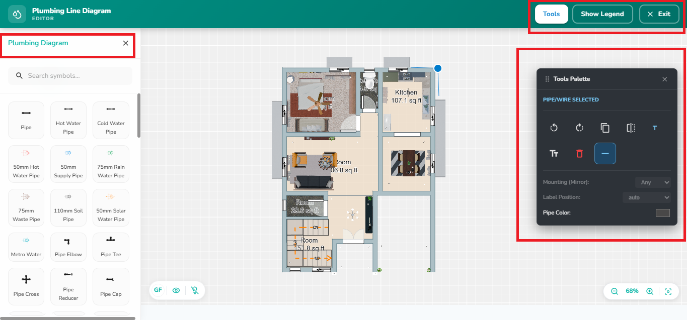
The Plumbing Diagram Panel contains plumbing symbols and components required for creating plumbing line layouts.
Steps
- Open MEP → Plumbing Diagram Editor.
- Use the search bar to find required plumbing symbols.
- Select a plumbing component from the library.
- Place the component on the floor plan.
- Connect components using pipes to create the plumbing layout.
Available Components
- Pipe
- Hot Water Pipe
- Cold Water Pipe
- 50mm Hot Water Pipe
- 50mm Supply Pipe
- 75mm Rain Water Pipe
- 75mm Waste Pipe
- 110mm Soil Pipe
- 50mm Solar Water Pipe
- Metro Water Connection
- Pipe Elbow
- Pipe Tee
- Pipe Cross
- Pipe Reducer
- Pipe Cap
- Additional plumbing fittings and accessories
Tools Menu #
The Tools menu provides drawing and editing functions for creating and modifying plumbing connections.
Steps
- Click Tools from the top toolbar.
- Select the required drawing or editing tool.
- Create or modify plumbing pipe layouts.
- Apply changes to the selected plumbing elements.
Show Legend #
Displays a reference legend containing all plumbing symbols used within the layout.
Steps
- Click Show Legend.
- Review the symbols and their meanings.
- Use the legend for design verification and documentation.
Tools Palette #
The Tools Palette enables editing and customization of selected pipes and plumbing components.
Available Functions
- Rotate Left
- Rotate Right
- Duplicate
- Mirror
- Add Label
- Delete
- Pipe Editing Tool
- Additional Modification Options
Property Settings
- Mounting (Mirror): Adjusts component orientation.
- Label Position: Defines label placement.
- Pipe Color: Changes the color of selected pipes.
Steps
- Select a pipe or plumbing component.
- Use the available editing tools from the Tools Palette.
- Modify properties as required.
- Changes are automatically reflected in the layout.
Exit Plumbing Diagram Editor #
Closes the Plumbing Diagram Editor and returns to the MEP workspace.
Steps
- Click Exit in the top-right corner.
- Save changes if prompted.
- Return to the previous workspace.
Note #
The Tools Palette becomes active when a pipe or plumbing component is selected. Use appropriate pipe types and fittings to create accurate plumbing system layouts.
3. Structural Diagram Editor #
The Structural Diagram Editor enables you to create and modify structural layouts by placing columns, beams, circles, and MAT foundations.
It provides editing tools and property controls to define structural elements accurately within the building framework.
Structural Diagram Panel #
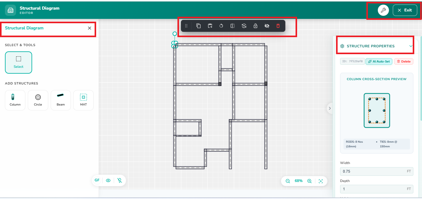
The Structural Diagram Panel provides tools for selecting and creating structural elements.
Steps
- Open MEP → Structural Diagram Editor.
- Select the required structural tool.
- Place structural elements on the workspace.
- Adjust the position and dimensions as needed.
- Review the structural layout.
Available Structure Tools
- Select: Select and modify structural elements.
- Column: Add structural columns.
- Circle: Create circular structural elements.
- Beam: Add beam members between structural supports.
- MAT: Create mat foundation layouts.
Editing Toolbar #
The Editing Toolbar provides quick actions for modifying selected structural elements.
Available Actions
- Copy
- Duplicate
- Undo
- Mirror
- Rotate
- Lock / Unlock
- Show / Hide
- Delete
Steps
- Select a structural element.
- Choose the required editing action from the toolbar.
- The selected element is updated immediately.
Structure Properties #
The Structure Properties panel allows you to configure dimensions and reinforcement details of the selected structural element.
Available Options
- AI Auto-Set
- Delete
- Column Cross-Section Preview
- Width
- Depth
- Reinforcement Details
- Tie Spacing
- Additional structure-specific properties
Steps
- Select a structural component.
- Open the Structure Properties panel.
- Modify the required dimensions and settings.
- Verify the preview before continuing.
Exit Structural Diagram Editor #
Closes the Structural Diagram Editor and returns to the MEP workspace.
Steps
- Click Exit in the top-right corner.
- Save changes if prompted.
- Return to the previous workspace.
Note #
Select a structural element to access its properties and editing options. The Structure Properties panel updates automatically based on the selected component.


