This guide outlines the general workflow for modifying various types of assets in your 2D floorplan, specifically the property fields for each item category.
Zlendo Realty provides two distinct workflows to modify your design assets depending on the depth of customization required:
1. The Right-Side Properties Panel for basic editing: Use the asset properties box to modify standard dimensions, structural coordinates, orientation angles, and basic layout parameters.
– Best for quick, high-level adjustments directly on your main canvas.
2. The Advanced Asset Editors: Use the asset editors to launch an isolated, full-screen detailing workspace via the floating toolbar.
– Best to handle intricate surface detailing for multiple layers, including editing materials, textures and colors, with specialized toolsets tailored to specific asset classes.
Zlendo Workspace Right-Side Panel #
Based on the element selected in your 2D workspace, the right-side panel in Zlendo Realty Editor’s Workspace dynamically adapts to display: 2D/3D Preview box, Asset Properties box, Default Design measurements box and View Settings box.
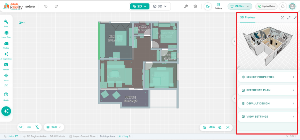
Right-Side Panel: Asset Properties Basic Editing #
The Properties box in the Right-side panel dynamically adapts to different asset types (Wall/Doors/Windows [Hole], Structure/Rooms [Area]/item) displaying the selected asset’s dimensions, position coordinates, elevation etc. as applicable.
Wall Configuration & Editing #
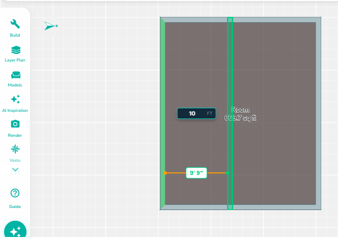
Wall Configuration & Editing provides access to wall properties and editing tools. Use the properties panel to adjust wall dimensions, materials, and alignment settings, and use the editor options to perform actions such as Split, Offset, Extend, Merge, Fillet, Hide, and Delete on selected wall segments.
Wall Properties #
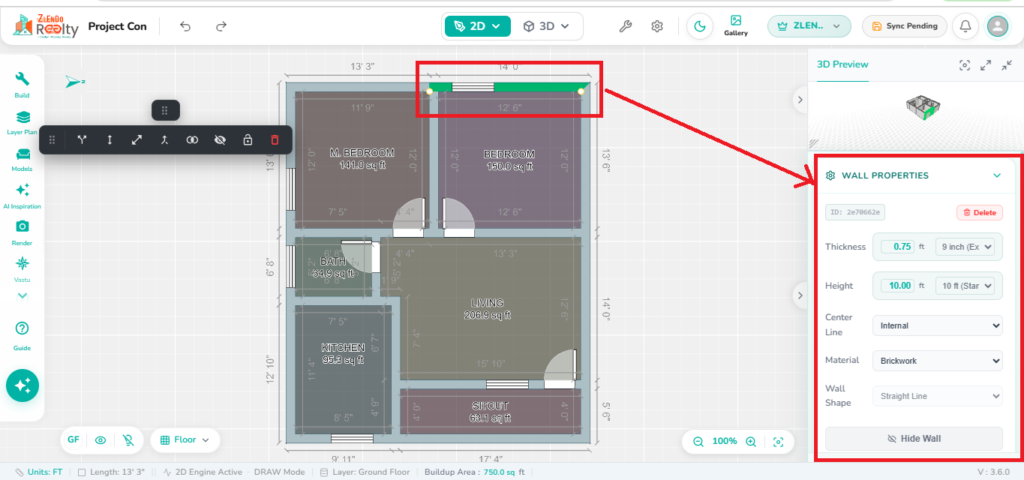
The Wall Properties panel appears on the right side when a wall is selected. It allows you to configure the wall’s dimensions, alignment, and material settings.
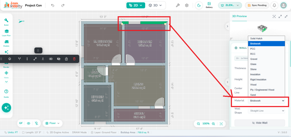
Material: A dropdown material mapping selector (e.g., Solid Hatch, Brick) to set the structural composition texture or color styling.
ID: Displays the unique system registration code for that specific wall segment.
Thickness: A slider and text box (e.g., 0.75 ft) to alter the width/thickness of the selected wall layout.
Height: A slider and text box (e.g., 10.0 ft) to determine how tall the wall stands when rendered in 3D views.
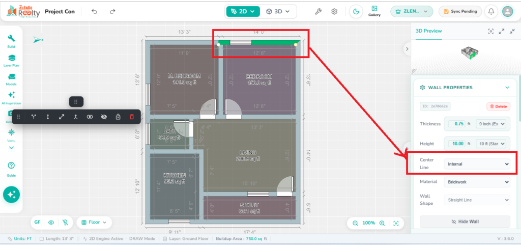
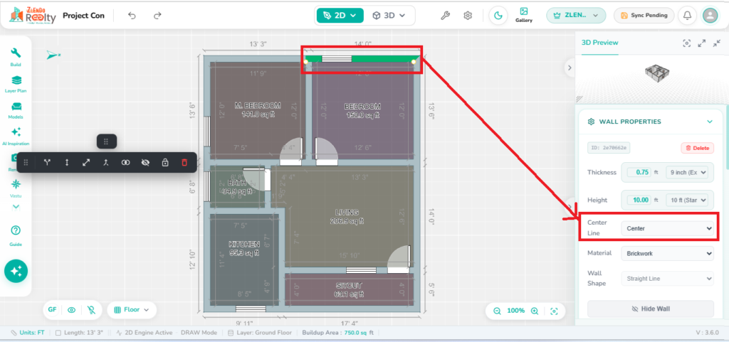
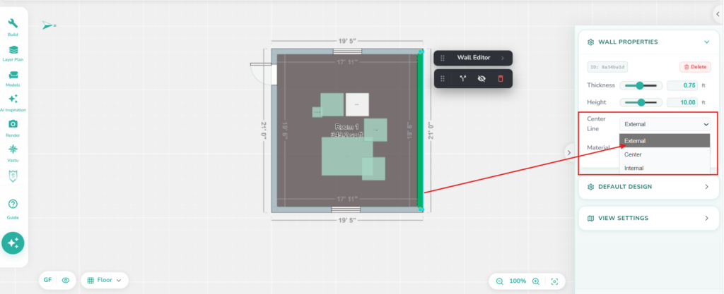
Center Line: A dropdown alignment selector used to define how wall-to-wall measurements are referenced and displayed. Available options include Internal, Center, and External. Users can also quickly cycle through these alignment modes using the Spacebar shortcut key, where each press switches between Internal → Center → External.
Wall Edit Option #
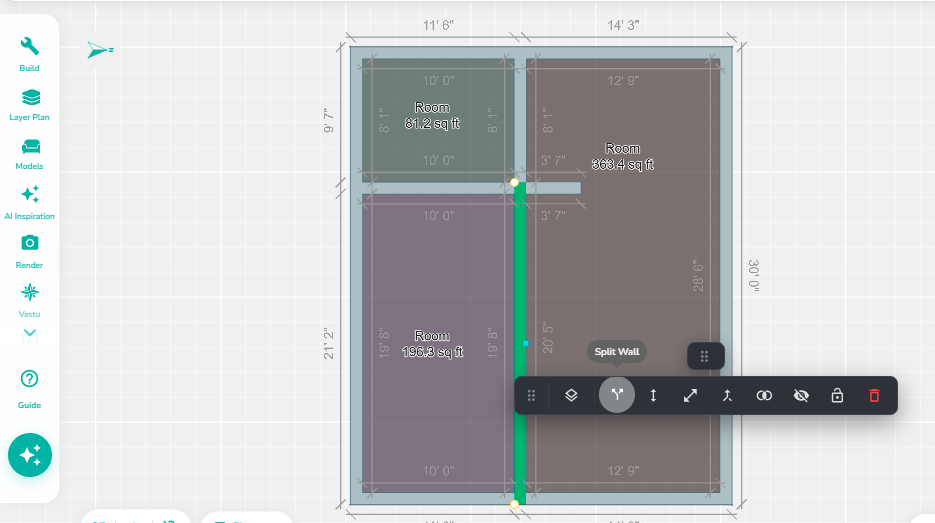
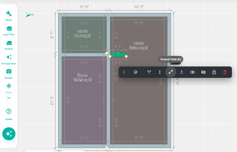
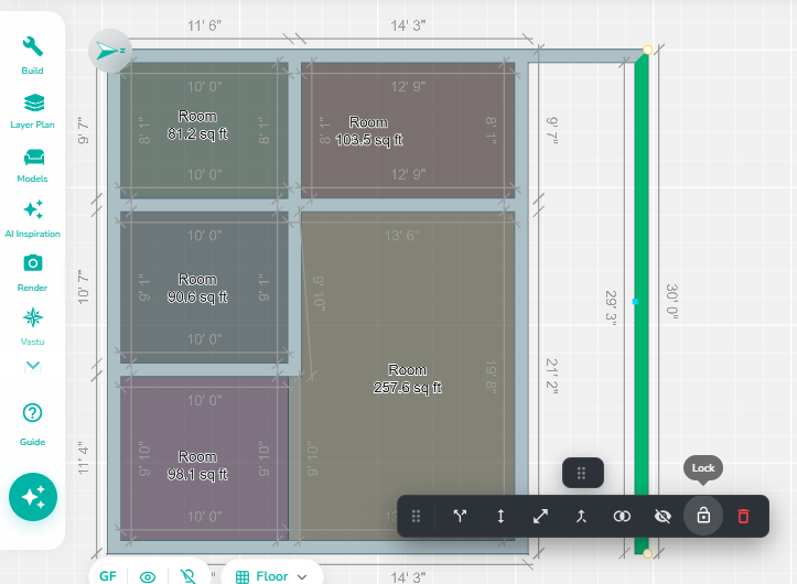
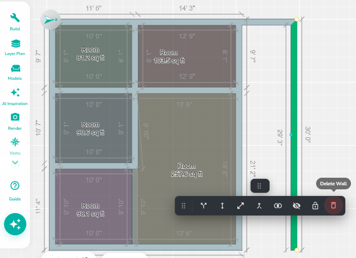
The Wall Editor Options pop-up toolbar appears near the selected wall and provides quick editing actions.
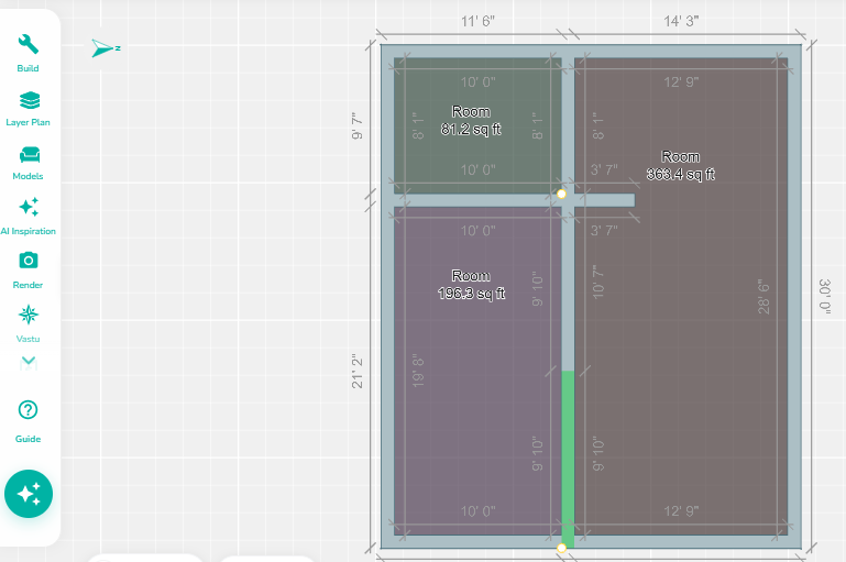
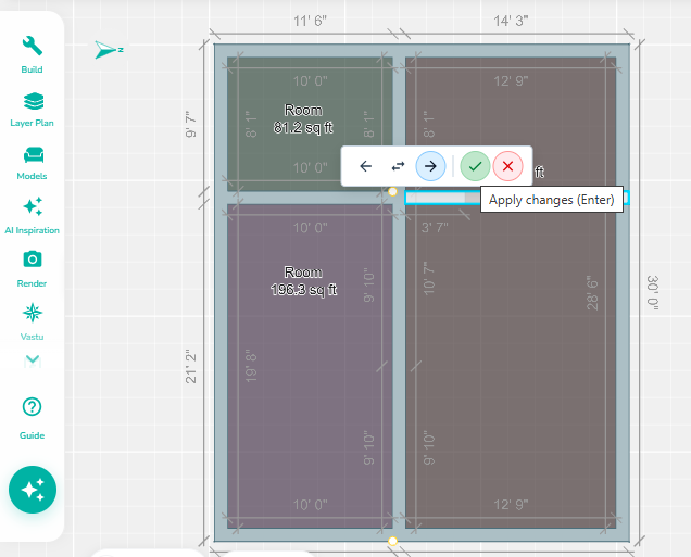
Split: Divides the selected wall into separate segments for easier editing and modification.
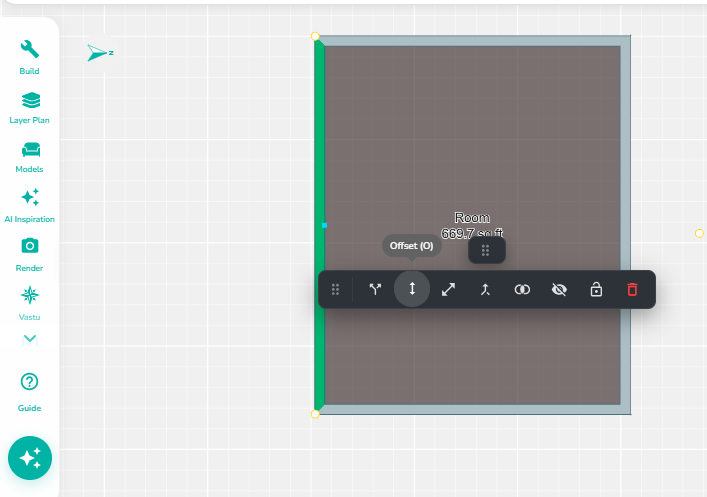
Offset (Shortcut: O): Creates a parallel wall at a specified distance from the selected wall.
Extend (Shortcut: E): Extends the wall length until it intersects with another wall or boundary.
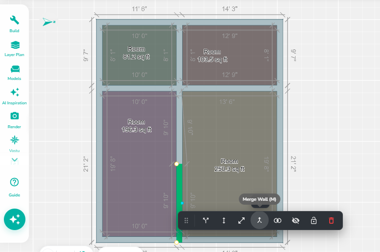
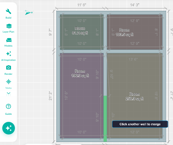
Merge (Shortcut: M): Combines adjacent wall segments into a single continuous wall.
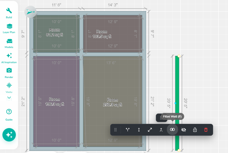
Fillet (Shortcut: F): Creates a rounded or connected corner transition between intersecting walls.
Hide Wall: Temporarily hides the selected wall from the current floor plan view.
Lock Wall: Temporarily hides the selected wall segment from the floor plan without deleting it. Hidden walls can be made visible again when needed, allowing users to focus on specific areas of the design while preserving the wall data.
Delete Wall: Permanently removes the selected wall segment from the project layout.
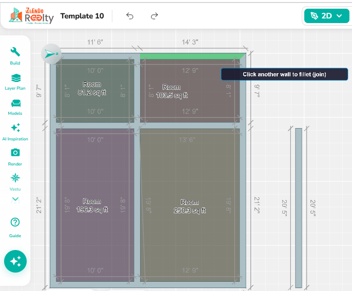
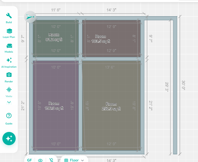
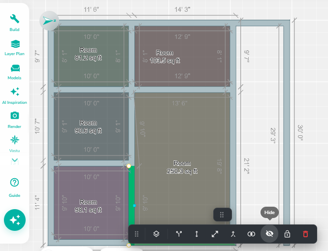
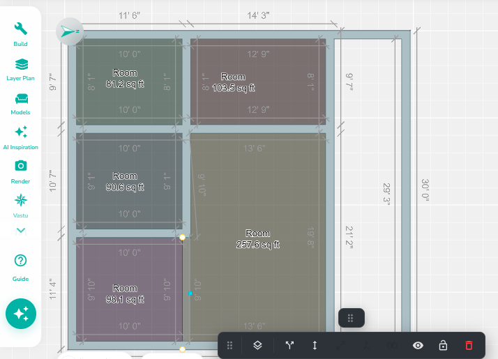
Arc / Curved Wall Properties and Modification Tools #
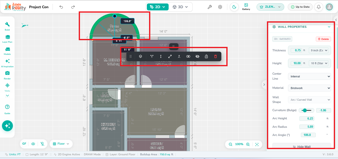
The Arc / Curved Wall Properties panel allows users to define the dimensions, geometry, material, and positioning of a curved wall. The modification toolbar provides additional editing tools for adjusting and managing the selected wall.
Curved Wall Properties #
Wall ID #
Displays the unique identification number assigned to the selected curved wall. This ID helps track and distinguish individual wall segments within the project.
Delete #
Permanently removes the selected curved wall from the floor plan.
Thickness #
Defines the width of the curved wall. Increasing or decreasing the value adjusts the physical wall thickness while maintaining the wall curvature.
Height #
Specifies the vertical height of the curved wall. Changes are reflected in both 2D and 3D views.
Center Line #
Determines the wall alignment reference used for positioning. For curved walls, options such as Internal, Center, or External alignment control how the wall is placed relative to its curve path.
Material #
Assigns the construction material to the wall, such as Brickwork. The selected material influences the wall’s representation and construction details.
Wall Shape #
Displays the current wall type. For this wall, the selected shape is Arc / Curved Wall, enabling arc-based wall geometry.
Curvature (Bulge) #
Controls the amount of curvature applied to the wall. Increasing the bulge creates a more pronounced curve, while reducing it makes the wall flatter.
Arc Height #
Displays and controls the height of the arc measured from the chord line to the highest point of the curve. Adjusting this value changes the shape of the curved wall.
Arc Radius #
Defines the radius of the curved wall. Larger values create wider curves, while smaller values result in tighter arcs.
Arc Angle (°) #
Specifies the angle covered by the curved wall segment. Changing the angle increases or decreases the arc span of the wall.
Hide Wall #
Temporarily hides the selected curved wall from the workspace without deleting it from the project.
Curved Wall Modification Tools #
Split #
Divides the selected curved wall into separate wall segments at the specified location, enabling independent editing of each segment.
Offset #
Creates a parallel copy of the selected curved wall at a specified distance. This tool is useful for generating adjacent walls or layered structures.
Extend #
Increases the length of the curved wall by extending its endpoints while maintaining the wall’s curvature characteristics.
Merge #
Combines two connected wall segments into a single wall where applicable, simplifying wall management and editing.
Fillet #
Creates a smooth curved transition between intersecting wall segments, reducing sharp corners and improving wall continuity.
Hide #
Temporarily conceals the selected wall from the workspace while keeping it available within the project.
Lock #
Locks the selected wall to prevent accidental movement, resizing, or modification during editing.
Delete #
Permanently removes the selected wall and its associated properties from the floor plan.
Roof Creation #
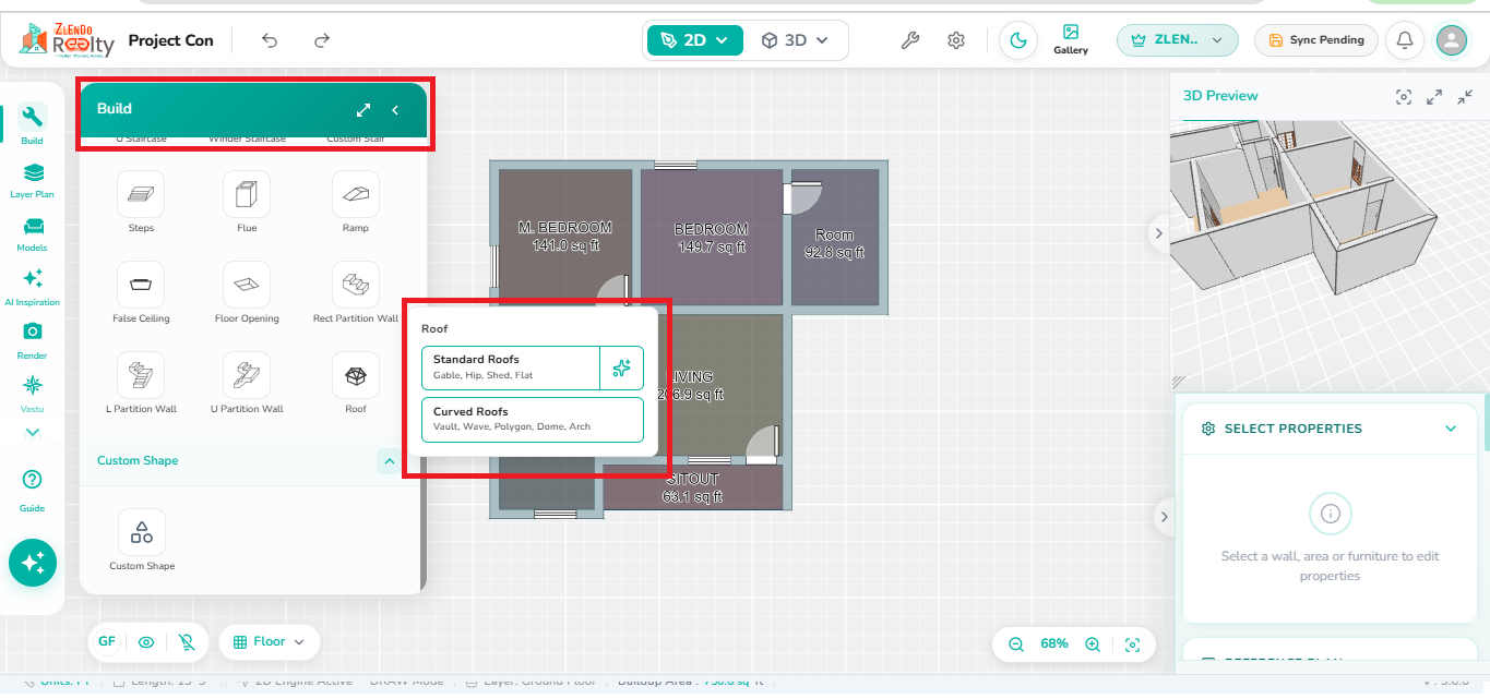
The Roof tool enables users to quickly create roof structures for their building design. Two roof creation methods are available: Standard Roofs and Curved Roofs. Users can choose the appropriate roof type based on the architectural style and project requirements.
Standard Roofs #
The Standard Roofs option is used to generate common roof styles such as Flat Roofs and Hip Roofs. The roof can be created using either AI-Based generation or Manual creation methods.
Available Methods
AI-Based Roof Creation #
The AI-Based option automatically analyzes the building shape and generates a roof that fits the structure.
Flat Roof #
- Creates a flat roof automatically based on the outer wall boundaries.
- Suitable for modern and contemporary building designs.
- The roof is generated instantly without manual adjustments.
Hip Roof #
- Automatically creates a hip roof that follows the building footprint.
- Sloped roof surfaces are generated based on the building geometry.
- Ideal for traditional and residential architectural designs.
Manual Roof Creation #
- Allows users to create and customize roof structures manually.
- Users can define roof geometry and make adjustments as required.
- Suitable when specific roof configurations are needed.
Curved Roofs #
The Curved Roofs option allows users to create customized curved roof structures with unique architectural forms.
Available Curved Roof Types
Vault Roof #
Creates a continuous arched roof spanning across the structure.
Wave Roof #
Generates a roof with a wave-like profile for modern architectural designs.
Polygon Roof #
Creates a roof based on multiple connected polygon segments.
Dome Roof #
Generates a dome-shaped roof structure commonly used for large covered spaces.
Arch Roof #
Creates an arched roof profile with smooth curved geometry.
Curved Roof Properties and Modification Tools #
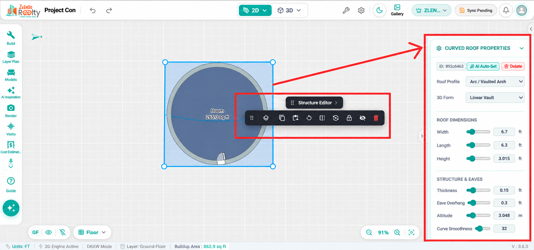
The Curved Roof Properties panel allows users to customize the shape, dimensions, structural settings, and appearance of a curved roof. The modification toolbar provides tools for editing and managing the selected roof after creation.
Curved Roof Properties #
Roof ID #
Displays the unique identification number assigned to the selected curved roof for project reference and management.
AI Auto-Set #
Automatically adjusts the curved roof dimensions and settings based on the underlying building geometry and selected roof profile.
Delete #
Permanently removes the selected curved roof from the project.
Roof Profile #
The Roof Profile property determines the geometric shape used to generate the curved roof. Selecting a roof profile changes the roof form and influences the overall architectural appearance of the structure.
Arc / Vaulted Arch #
Creates a smooth arched roof with a continuous curved surface. This profile is ideal for vaulted spaces, halls, auditoriums, and modern architectural designs that require an elegant curved roof structure.
Wave / Freeform Curve #
Generates a flowing wave-shaped roof with flexible curved geometry. This profile is suitable for contemporary and creative building designs where unique roof forms and organic shapes are desired.
Aerodynamic / Parabolic #
Creates a parabolic roof profile with an aerodynamic shape. This option is commonly used for large-span structures, sports facilities, commercial buildings, and modern architectural projects that benefit from efficient curved forms and distinctive visual appeal.
Usage #
Select the required Roof Profile from the dropdown list to instantly update the roof geometry. The available 3D Form and roof dimension settings adjust accordingly, allowing further customization of the selected roof type.
3D Form #
The 3D Form property defines how the selected roof profile is generated and extended in three-dimensional space. It controls the overall volumetric shape of the roof and determines how the roof appears in the 3D model.
Linear Vault #
Creates a continuous vaulted roof that extends uniformly along a straight direction. The curved profile is maintained across the entire roof length, making it suitable for corridors, halls, warehouses, and rectangular structures.
360° Dome / Cone #
Generates a complete radial roof form by revolving the selected profile around a central point. Depending on the chosen roof profile, this creates a dome-shaped or cone-shaped roof suitable for circular rooms, pavilions, gazebos, and architectural focal points.
Groin Vault #
Creates an intersecting vaulted roof formed by the crossing of two vaulted sections. This form is commonly used in classical and architectural designs where multiple curved roof spans meet, creating a visually distinctive and structurally efficient roof pattern.
Usage #
Select the required 3D Form from the dropdown menu to define how the roof profile is translated into a three-dimensional structure. The resulting roof geometry is automatically updated in both the workspace and the 3D preview, allowing users to visualize and refine the roof design.
Roof Dimensions #
Width #
Controls the overall width of the curved roof structure. Modifying this value changes the roof size across its horizontal span.
Length #
Defines the overall length of the curved roof. Adjusting this value extends or reduces the roof coverage.
Height #
Determines the vertical rise of the curved roof from its base. Higher values create a taller roof profile.
Structure & Eaves #
Thickness #
Defines the structural thickness of the roof. Increasing the thickness creates a deeper roof section.
Eave Overhang #
Controls how far the roof extends beyond the supporting walls. Overhangs provide additional coverage and improve the architectural appearance.
Altitude #
Sets the elevation of the roof above the floor level. Increasing the altitude raises the entire roof structure.
Curve Smoothness #
Controls the smoothness and refinement of the roof curvature. Higher values create smoother curved surfaces with improved visual quality.
Curved Roof Modification Tools #
Structure Editor #
Enables interactive editing of the curved roof geometry and boundary control points, allowing precise shape adjustments.
Copy #
Creates a duplicate of the selected curved roof while preserving all roof settings and properties.
Repeat #
Generates multiple copies of the selected roof based on the specified spacing and placement direction.
Rotate #
Rotates the roof to the desired orientation while maintaining its geometry and dimensions.
Mirror #
Creates a mirrored version of the selected curved roof for symmetrical roof layouts and designs.
Lock #
Locks the roof to prevent accidental movement, resizing, or editing.
Hide #
Temporarily hides the curved roof from the workspace without removing it from the project.
Delete #
Permanently removes the selected curved roof and all associated roof properties from the design.
Standard Roof Properties and Modification Tools #
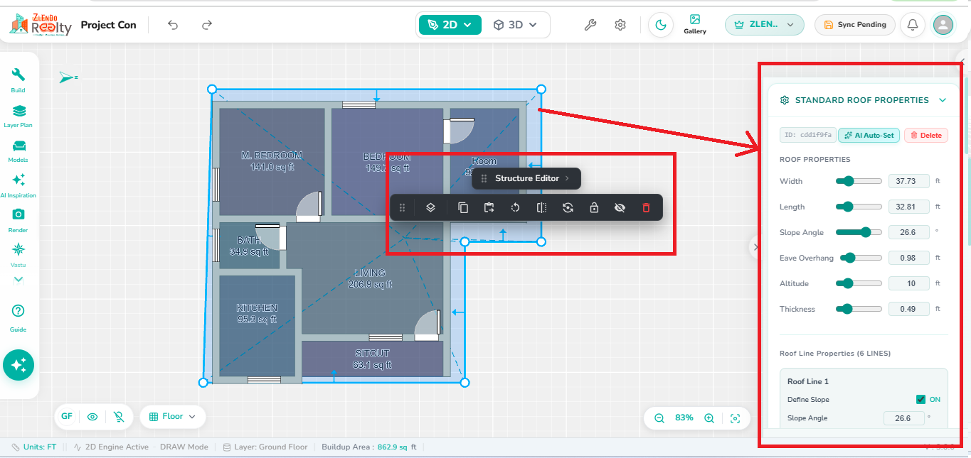
The Standard Roof Properties and Modification Tools allow users to customize roof dimensions, slope, overhang, elevation, and roof line settings after a roof has been created. The right-side properties panel provides precise control over the roof geometry, while the modification toolbar offers quick editing and management actions.
Standard Roof Properties #
Roof ID #
Displays the unique identifier assigned to the selected roof for project reference and management.
AI Auto-Set #
Automatically recalculates and adjusts roof parameters based on the building footprint and selected roof type. This helps quickly generate an optimized roof structure.
Delete #
Permanently removes the selected roof from the project.
Width #
Controls the overall width of the roof structure. Increasing or decreasing this value adjusts the roof size horizontally.
Length #
Defines the overall length of the roof. Modifying this value changes the roof’s coverage along the building footprint.
Slope Angle #
Specifies the inclination of the roof surfaces. Higher values create steeper roof slopes, while lower values produce a flatter appearance.
Eave Overhang #
Determines how far the roof extends beyond the exterior walls. Overhangs provide additional protection from sun and rain.
Altitude #
Sets the vertical elevation of the roof above the floor level. Increasing the altitude raises the roof position.
Thickness #
Defines the thickness of the roof structure, affecting both visual appearance and construction dimensions.
Roof Line Properties #
Roof Line #
Each roof edge can be individually configured using Roof Line settings to customize roof behavior and shape.
Define Slope #
Enables or disables slope generation for the selected roof line. When enabled, the roof surface will slope from that edge.
Roof Line Slope Angle #
Allows users to specify a unique slope angle for an individual roof line, providing greater control over roof geometry.
Standard Roof Modification Tools #
Structure Editor #
Enables direct editing of roof boundaries and roof line geometry. Users can adjust roof dimensions and reshape the roof interactively.
Copy #
Creates a duplicate of the selected roof that can be placed elsewhere in the design.
Repeat #
Generates repeated copies of the selected roof according to the specified spacing and direction.
Rotate #
Rotates the roof to the required orientation while maintaining its shape and properties.
Lock #
Locks the roof to prevent accidental movement or modification during editing.
Hide #
Temporarily hides the roof from the workspace without removing it from the project.
Delete #
Permanently removes the selected roof from the design and deletes all associated roof settings.
Common Modify and Hole Properties #
Modify Properties: Door, Window and Opening. #
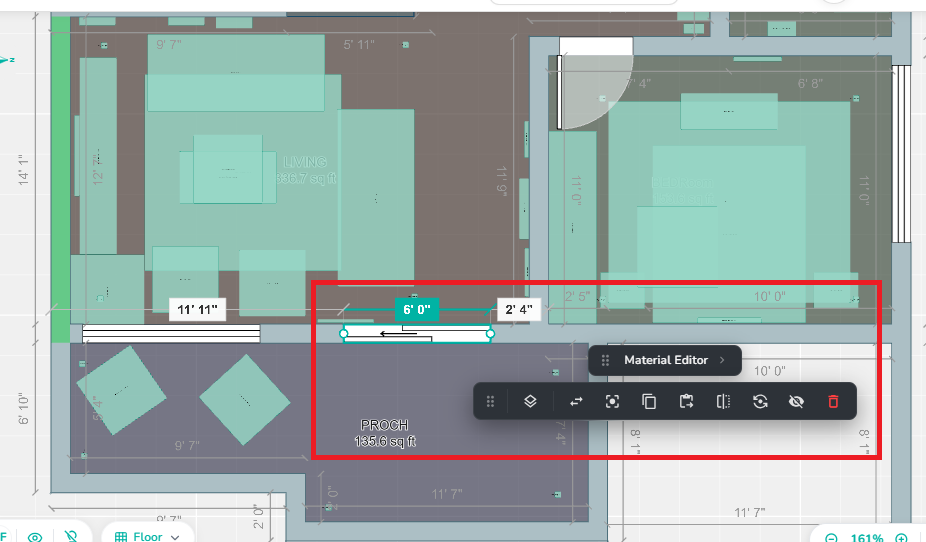
Common Properties for Doors, Windows, and Openings
Replace #
Use the Replace option to substitute the selected door with another door style, type, or size while maintaining its placement in the wall.
Center Fit #
Use Center Fit to automatically position the selected door at the center of the available wall opening for accurate alignment.
Copy #
Use Copy to create a duplicate of the selected door and place the copied door at another location within the current floor plan.
Copy Floor #
Use Copy Floor to duplicate the selected door to another floor while preserving the same position, orientation, and door properties.
Flip Horizontal #
Use Flip Horizontal to mirror the selected door along the horizontal axis, changing its opening direction or swing orientation.
Flip Vertical #
Use Flip Vertical to mirror the selected door along the vertical axis and adjust its orientation within the wall layout.
Hide #
Use Hide to temporarily conceal the selected door from the workspace without deleting it from the project.
Delete #
Use Delete to permanently remove the selected door from the current project layout. This action deletes the door from the design model.
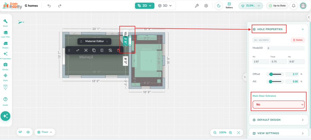
Hole Properties: Windows & Openings #
Windows function as wall-hosted openings. Openings are wide entrances into rooms.
Model ID: Displays the design style identity reference.
Dimensions (Wi / Thick / He): Controls the Width of the window span, structural wall-match Thickness, and total vertical Height.
Offset: A positioning slider that slides the window left or right along the length of its host wall.
Alt (Altitude): Determines the sill height level (how high off the ground floor the window opening starts).
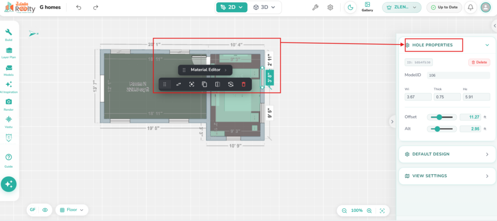
Hole Properties: Doors & Entrances #
Doors share the structural wall-hosted properties of windows but add unique residential entrance classification traits.
Dimensions (Wi / Thick / He): Sets the opening Width, frame Thickness, and clearance walk-through Height.
Offset & Alt: Slides the placement door entry pathway horizontally along the wall line, and sets threshold altitude elevations (typically set to 0.00 ft for standard floor level lines).
Main Door Entrance: A specialized dropdown toggle selecting Yes or No to establish whether this asset registers as the primary boundary threshold entry point for the estate plan.
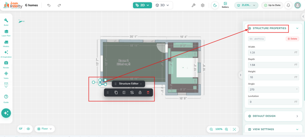
Structure Properties: Columns, Pillars & Beams, Stairs #
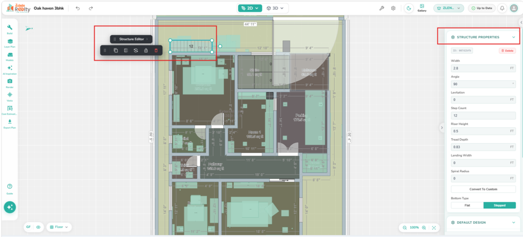
Structural items are critical engineering-related building blocks that are necessary for accurate architectural support detailing. When editing structural assets directly in the 2D layout canvas, selecting the element brings up the right-hand Structure Properties card.
ID: Displays the unique architectural database registration tag assigned to that specific component instance.
Width: Controls the horizontal cross-section width of the structural object (e.g., expanding a column’s profile thickness).
Depth: Adjusts the orthogonal horizontal baseline thickness or span length of the asset along the grid.
Height: Controls the absolute vertical protrusion height of the asset (e.g., extending a column to seamlessly hit the ceiling deck, or setting staircase elevations).
Angle: A precise rotation block (ranging from 0° to 360°) that pivots the structural asset orientation relative to your adjacent wall systems or room corners.
Levitation: Adjusts the baseline float clearance distance off the primary ground floor level line (0.00 ft).
Application: Keep at 0 for ground-floor pillars and staircases or increase the value to cleanly suspend structural overhead crossbeams right against your high ceiling structures.
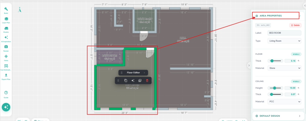
Area Properties: Floors & Ceilings #
Clicking inside a room activates the floor & ceiling area properties to be displayed on the right-side panel.
Floor Configurator
Label: A customizable text line to rename spaces (e.g., Room 2, Master Bedroom, Kitchen).
Type: A category dropdown selector to define the room Name (e.g., Living Room).
Floor Configurator: * Features a Visible visibility state switcher icon.
Thick: A slider to set structural floor deck slab thickness layers.
Material: Flooring material/finish picker dropdown (e.g., Stone, Tile, Hardwood).
Ceiling Configurator
Height: Vertical clearance ceiling drop heights relative to floor plans.
Thick: Adjusts upper roof joist/ceiling deck slab thickness bounds.
Material: Changes overhead surface finish matrices (e.g., PCC, Plaster).
Item Properties and Modify Tools #
Item Properties: Furniture & Standalone Models #
When a standalone object or furniture model is selected, the panel manages 3D space placement vectors.
Model ID: Displays the backend catalog identification number for the asset.
Dimensions (Wi / De / He): Precise text input boxes to change the Width, Depth, and Height scale metrics.
Pos X / Pos Y: Precise coordinate position sliders to slide objects along the grid floor path.
Alt (Altitude): Height adjustment slider to levitate items off the floor level (e.g., ceiling lamps).
Rot (Rotation): A slider or input box ranging from 0° to 360° to pivot the asset orientation angle.
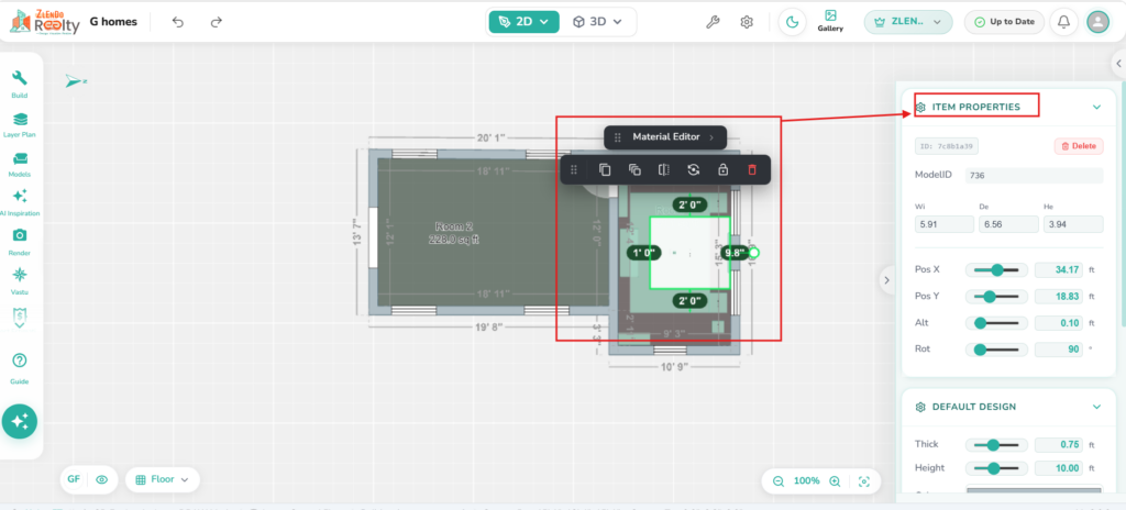
Item Modify Tool: Furniture & Standalone Models #
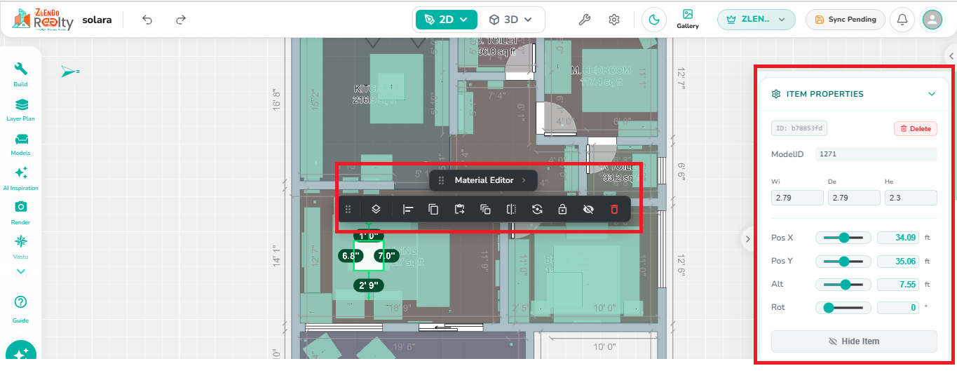
The Asset Properties panel allows users to view and modify the characteristics of a selected asset within the design workspace. Users can adjust the asset’s dimensions, including width, depth, and height, and precisely control its placement using X and Y position coordinates. Additional settings such as altitude and rotation enable accurate alignment and positioning within the project. The panel also provides quick actions.
1. Select Object #
Select a specific asset in the workspace to view, edit, or modify its properties. This tool helps users focus on an individual object for precise adjustments and asset management.
2. Align #
Align the selected asset with walls, nearby assets, or reference points to ensure accurate positioning and consistent layout within the design.
3. Copy #
Create a duplicate of the selected asset while retaining its dimensions, orientation, and properties. The copied asset can be placed elsewhere in the project.
4. Paste to Floor #
Paste the copied asset onto another floor while maintaining its original placement and settings. This feature simplifies asset replication across multiple floors.
5. Mirror #
Create a mirrored copy of the selected asset across a specified axis. This is useful for creating symmetrical layouts and repeating design elements efficiently.
6. Flip Horizontal #
Reverse the selected asset along the horizontal axis, creating a left-to-right reflection while keeping the asset in the same location.
7. Flip Vertical #
Reverse the selected asset along the vertical axis, creating a top-to-bottom reflection without changing its position in the workspace.
8. Lock #
Lock the selected asset to prevent accidental movement, rotation, resizing, or modification during the design process.
9. Hide #
Temporarily hide the selected asset from the workspace view without deleting it. Hidden assets can be displayed again whenever needed.
10. Delete #
Permanently remove the selected asset from the project. Once deleted, the asset will no longer appear in the workspace unless restored using the undo action.
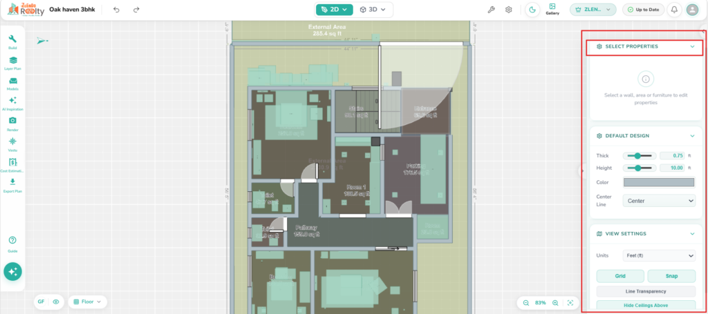
Right-Side Panel: Default Design #
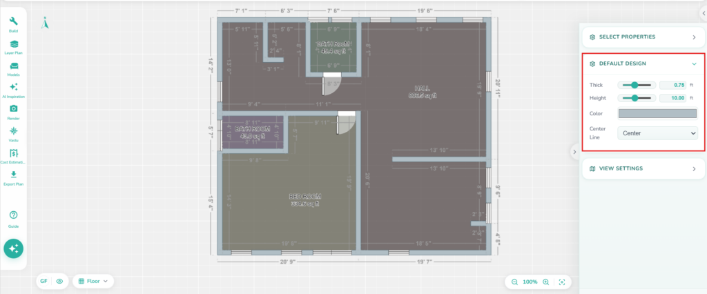
Default Design allows you to edit the structural properties for all new walls you draw. Configuring these parameters beforehand eliminates the need to manually adjust every single wall segment later.
Thickness (Line): Use the slider or type a precise numerical value to set the default core thickness for all new walls.
Height (Line): Use the slider or enter a custom value (preset to 10.0 ft) to establish the standard height clearance for your walls when rendered in 3D visualization modes.
Colour: Displays a visual swatch bar showing the preset baseline fill color or pattern hatch applied to newly drawn walls.
Alignment: A justification dropdown menu (set to Center by default) that dictates how new wall thickness spreads relative to your drawing path line (Center, External, or Internal).
Right-Side Panel: View Settings #
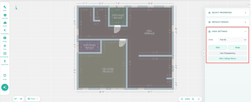
View Settings has toggle commands to customize layout visibility styles, alignment grids, and snap controls on your design canvas.
📏 Units: A dropdown menu to select the measurement format for the workspace (currently set to Feet (ft)).
⌗ Grid: A toggle button to turn the background workspace grid alignment lines on or off (currently active/selected).
✛ Snap: A toggle button to enable or disable automatic snapping to elements, endpoints, or intersections while drawing (currently active/selected).
🪄 Line Transparency: A setting button to adjust the visibility or transparency levels of drawing/layout lines. (Will be viewable in 3D preview on top when you turn line transparency on or off.)
👁️🗨️ Hide Ceilings Above: A visibility toggle button used to clear or hide ceiling structures when viewing the layout in 3D mode.
Multi-Selection Properties Editing and Modification Tools #
Multi-Selection: Properties Editing #
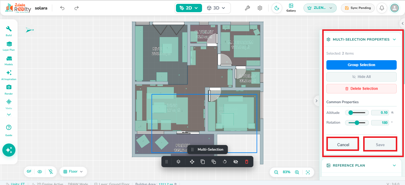
The Multi-Selection Properties Editing feature allows users to select multiple objects by holding the Shift key and clicking the required items. Once selected, users can modify common properties and perform editing operations on multiple objects simultaneously and click on Save or Cancel.
When objects of the same type are selected, such as multiple Beds, Doors, or Windows, all shared properties available for that object category are displayed and can be edited together.
Multi-Selection: Modification Tools #
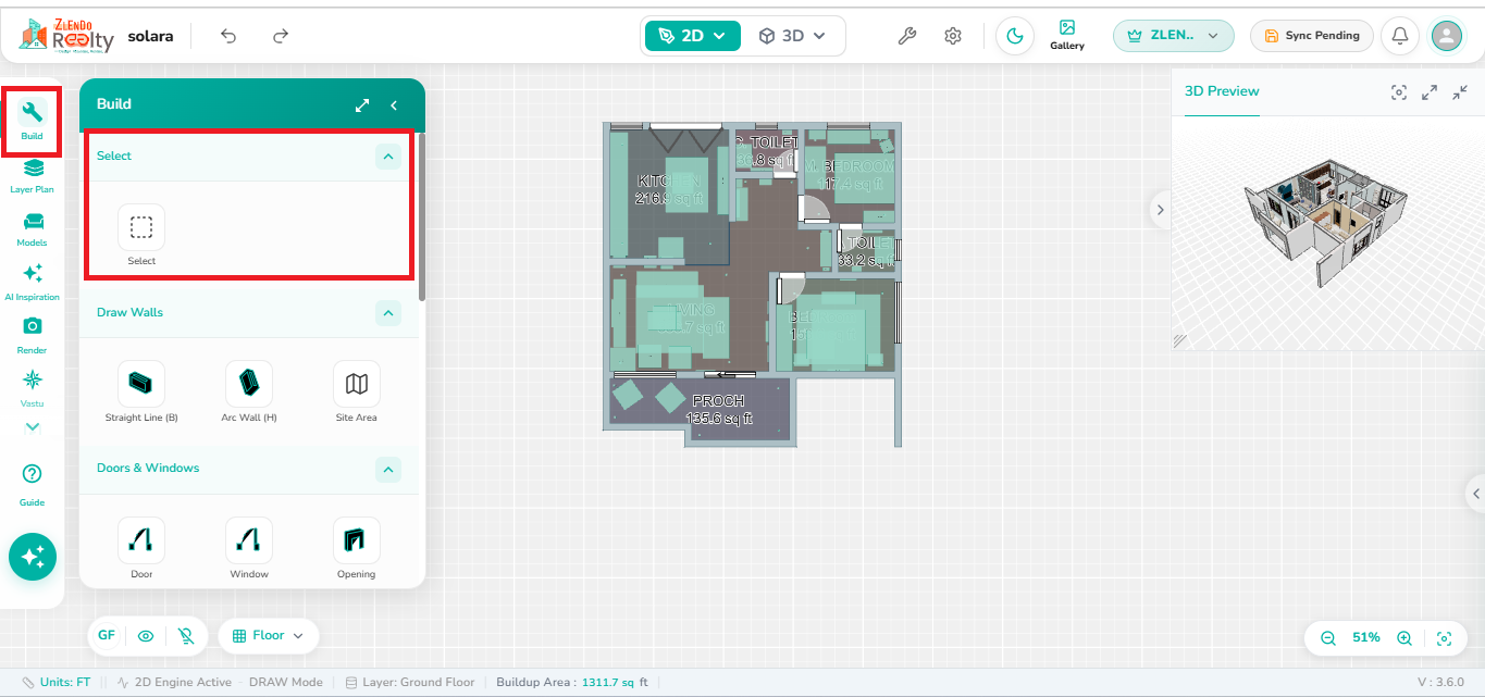
The Select option in the Build Tool allows users to select one or multiple objects within the floor plan for editing. Once an item is selected, a contextual modification toolbar appears, providing quick access to commonly used editing actions like Move, Copy, Mirror, Rotate, Hide, and Delete. This tool simplifies object management and enables efficient modification of floor plan components.
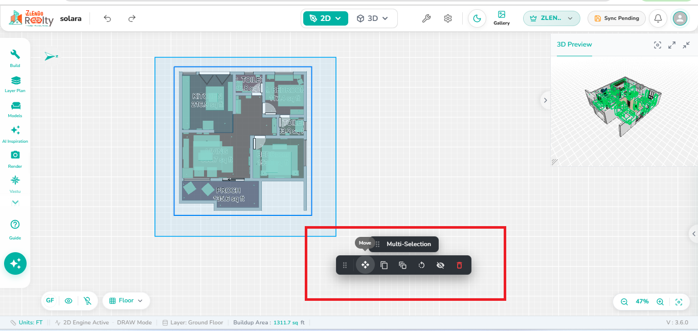
Individual Action Descriptions #
Move #
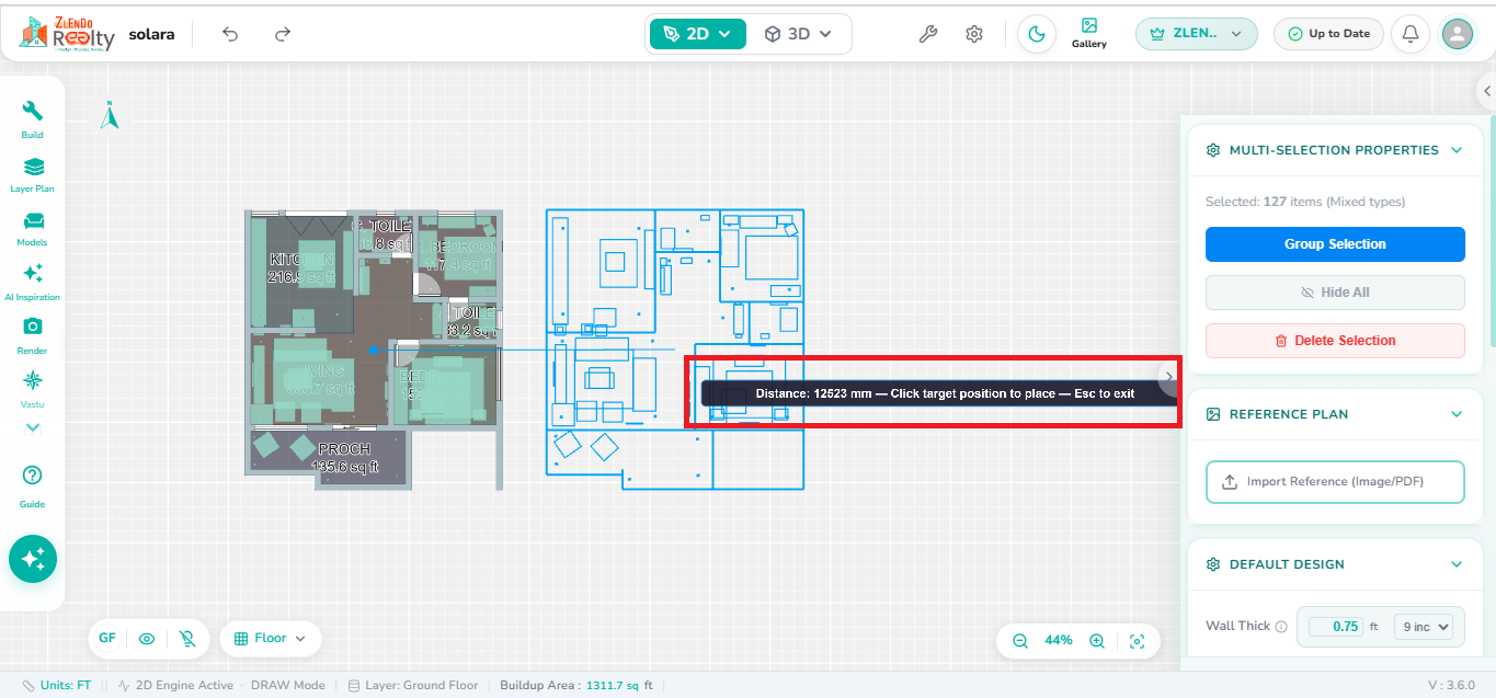
Moves the selected object or group of objects to a new location while maintaining their properties.
Copy #
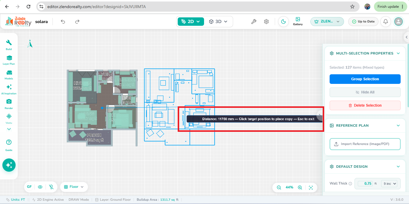
Creates an identical copy of the selected item that can be placed elsewhere in the design.
Mirror #
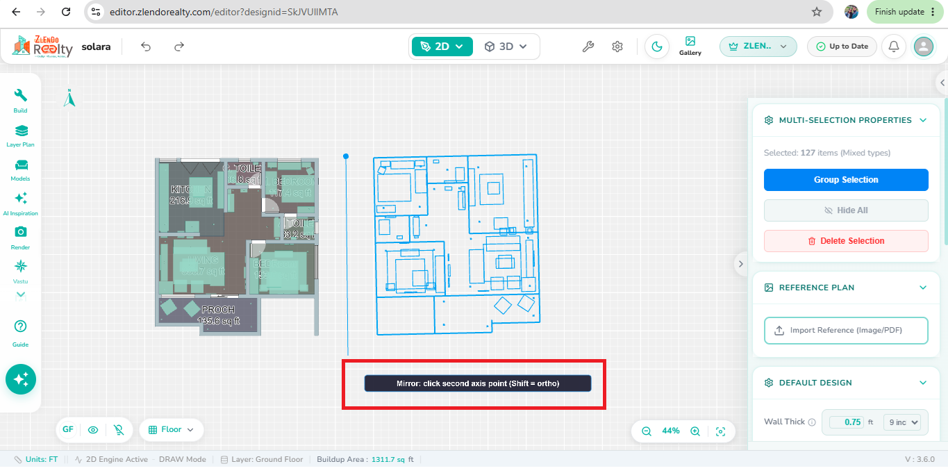
Reflects the selected object horizontally or vertically to achieve symmetrical layouts.
Rotate #
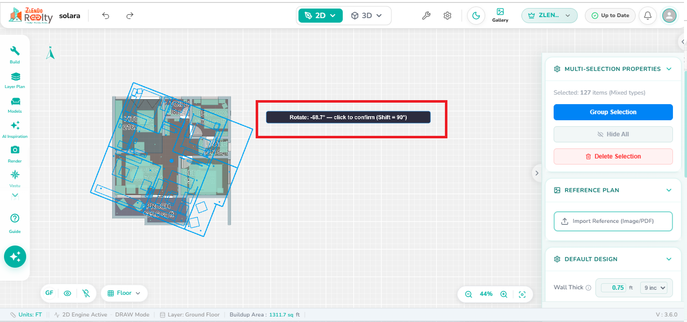
Rotates the selected item to the required angle for accurate placement and alignment.
Hide #
Temporarily hides the selected elements without deleting them from the project.
Delete #
Permanently removes the selected object or group of objects from the design workspace.
Advanced Asset Customization #
Zlendo Realty also features an expansive Asset Customization editor that allows a designer to create complex surface detailing quickly and easily.
Using the Advanced Editor you can fine-tune physical properties, change textures or color, create patterns add any asset to your floor plan.
Wall & Structure / Floor / Ceiling / Material Editors #
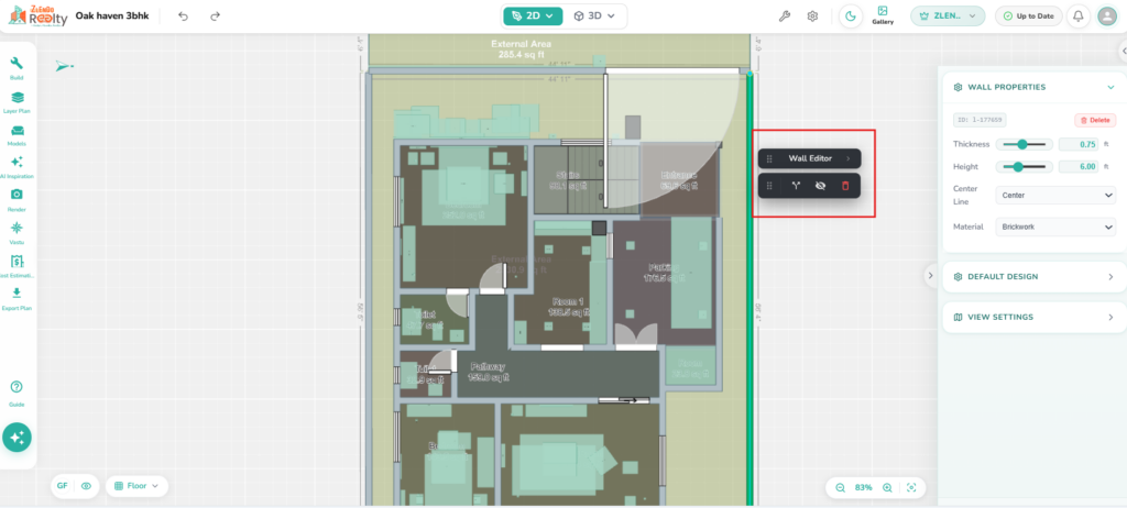
Depending on the type of element/asset you select on your floorplan, clicking the floating Editor bar next to it opens the asset’s Customization Editor tailored precisely to that asset type.
Accessing the Customization Suite #
| Advanced Customisation Editor Type | Trigger Condition | Primary Functionality |
| 🧱 Wall Editor | Click on any Individual Wall Segment | Allows independent texture mapping for interior vs. exterior faces, custom vertical layout repeats, and non-uniform wall heights (e.g., creating gables, step-downs, or sloped surfaces). |
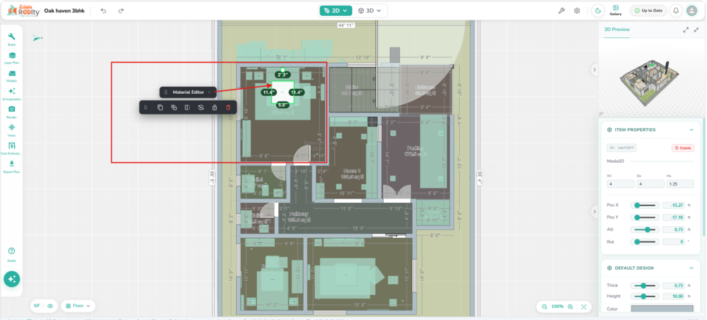
| 🪟 Materials Editor | Click on any Door, Window, Furniture, or Furnishing Model (e.g., Bed, Carpet) | Controls localized physical properties like texture intensity, alpha transparency blending, surface reflectivity, and customized hex color picking across distinct model components. |
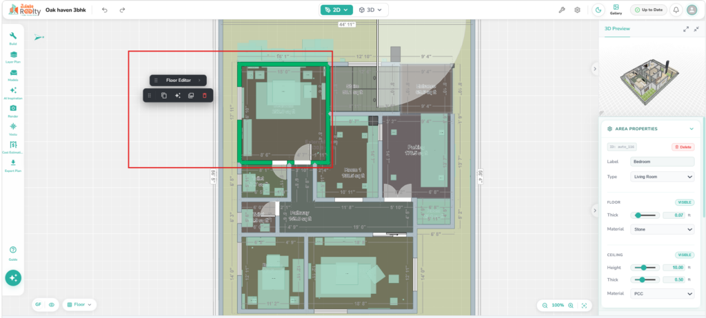
| 🪵 Floor Editor | Click inside an enclosed Room Area / Floor Boundary | Opens a dedicated spatial canvas focused on flooring configurations, calculating exact surface area/perimeter specs, and managing complex material tiles or custom paving orientations via the Paving Editor. |
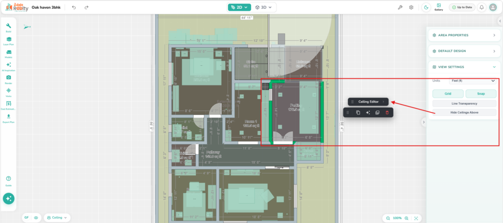
| 🏛️ Ceiling Editor | Click inside an enclosed room area or overhead plane while working in the Ceiling Layer | Opens an isolated overhead workspace to review room-specific area and perimeter metrics, apply paint colors or ceiling textures, and calibrate overhead pattern mapping. |
| 🏗️ Structural Editor | Click on any Structural Asset (e.g., Column, Beam, Staircase, or False Ceiling component) | Isolates core structural components to apply custom construction material finishes (concrete, brick, wood) or brand-matched solid color coats across specific structural layers. |
Select the Asset: In your 2D design workspace, click directly on the asset you want to customize.
Launch via Floating Toolbar: Look for the dark floating menu that instantly materializes next to your selection. Click on the prominent main button (e.g., Material Editor, Wall Editor, or Floor Editor).
Full-Screen Focus Mode: The editor will smoothly transition into a focused, full-screen detailing platform, temporarily tucking away standard canvas management toolbars so you can iterate on asset aesthetics with absolute precision.
🧱 Wall Editor #
Changing Wall Textures & Color #
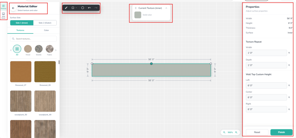
The advanced customization suite features a Textures tab that allows you to customize surface textures independently for each side of the walls, add pattern repeats & wall decor items, and set non-uniform wall heights.
Select Your Surface Side
Walls have two distinct faces. Before applying colors or textures, choose which side you are editing in the left panel:
Side 1 (Inner): Modifies the interior face of the wall segment.
Side 2 (Outer): Modifies the exterior face of the wall segment.
Browse and Apply Textures or Colors
Use the left sidebar inside the materials editor to style your selected surface side:
Textures Tab: Browse through categorized material thumbnails like Wood, Marble, or Fabric. Click any swatch (e.g., finewood 27, woodplank_50) to apply it instantly to the wall preview.
Color Tab: Switch to this tab if you prefer a solid paint finish rather than a textured material.
Current Texture Indicator: Look at the top-center card to instantly verify what material is currently active on your canvas.
If a textured material is active, navigate to the right-hand Properties panel to prevent the pattern from looking stretched or unrealistic:
– Width: Adjust how wide the texture pattern stretches before repeating.
– Depth: Adjust the vertical density or depth scaling of the applied pattern.
Configure Wall Top Custom Heights (Optional)
For standard layouts, walls remain uniform. However, if you are designing sloped roofs, gables, or step-up partitions, use the Wall Top Custom Height inputs at the bottom right to assign non-uniform vertical heights:
– Left: Sets the absolute height at the starting endpoint of the wall segment.
– Center: Controls the height at the midway vertex.
– Right: Sets the absolute height at the terminating endpoint of the wall segment.
Save or Reset Your Work
Reset: Click the white button at the bottom right to discard your recent surface alterations and revert to the baseline wall properties.
Finish: Click the green button to lock in your custom textures and dimensions and return to the main 2D workspace canvas.
Adding Wall Decor #
The advanced Wall customization editor suit features a Wall Decor tab that allows you to mount decorative assets, doors, moldings, and art sets directly onto a wall face. This guide explains how to accurately position and scale vertical decorations on your selected surface side.
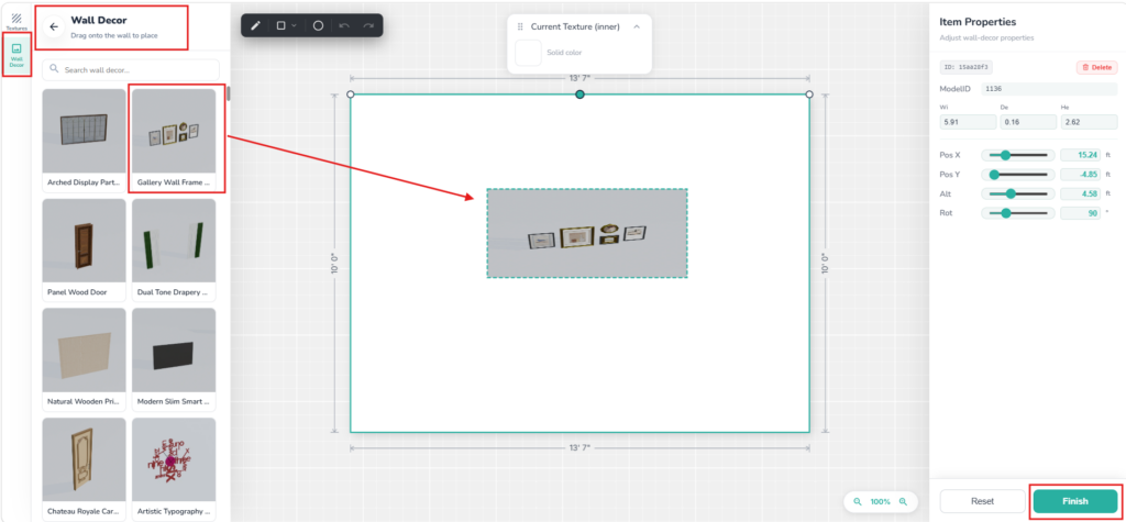
Place an Asset onto the Wall
Browse the item cards in the left panel to find accessories like the Gallery Wall Frame Set, Panel Wood Door, or Modern Slim Smart TV.
Click and drag your chosen item from the sidebar directly onto the central wall preview canvas.
Once dropped, a dashed boundary box will surround the asset, indicating it is active and selected for editing.
Configure Placement & Dimensions (Item Properties)
When an item is active on the wall face, the right-hand Item Properties panel updates to manage its precise physical placement vectors:
ModelID / ID: Identifies the system asset parameters and unique component layer tag.
Dimensions (Wi / De / He): Adjust text boxes to scale the object’s Width across the wall, Depth (how far it projects outwards from the wall face), and vertical Height.
Pos X / Pos Y: Use these precision sliders to slide the item left or right across the horizontal axis of the wall surface.
Alt (Altitude): Adjust this slider to change the height elevation off the floor lines (e.g., hanging a frame perfectly at eye-level or positioning a baseboard fixture right against the floor boundary).
Rot (Rotation): Rotates or tilts the asset orientation angles relative to the wall backing.
Save or Discard Changes
Reset: Click the white button at the bottom right to flush out any newly dragged decor additions or adjustments made during this edit session.
Finish: Click the green button to lock your artwork, doors, or panels seamlessly to the wall structure and return to your primary 2D layout workspace.
🏗️ Advanced Structure Asset Editor #
To customize a structural (load bearing or framework) element such as a column, pillar, beam, staircase, or false ceiling, click Structure Editor from the floating action bar.
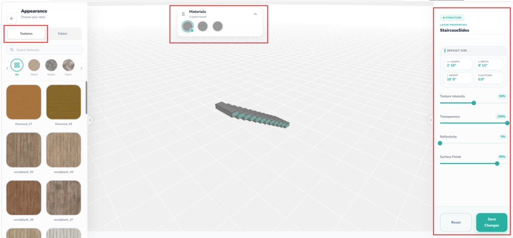
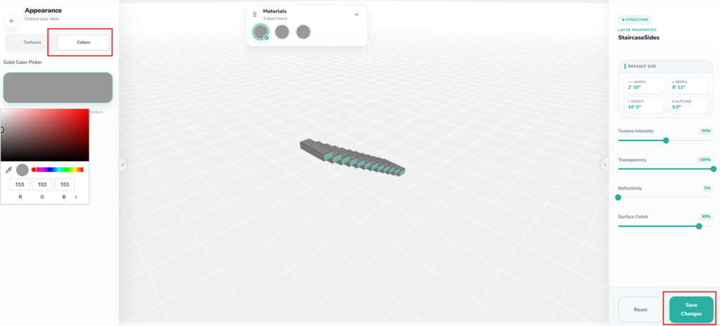
Verify the Component Structural Layer
Look at the top-center Materials floating badge to view/select the active component layers detected on your structural block (e.g., 1 layer).
Click on a layer to activate it. The right-hand panel confirms the specific Layer Properties for the chosen layer. Use this box to change any dimensional detail.
Choose Your Finish Path (Textures vs. Colors)
Use the left-hand Appearance sidebar panel to define the architectural finishes:
Textures Tab: Browse through professional building material categories including Wood, Marble, Fabric, or industrial finishes like concrete and brick. Click any swatch to instantly wrap the texture around your column, beam, or step geometry.
Colors Tab: Open the Solid Color Picker palette to apply uniform solid coats. You can adjust the visual canvas spectrum, manipulate the rainbow hue slider, or enter exact R / G / B coordinates to implement precise brand paint specs.
Refine Advanced Surface Parameters
To mimic real-world building materials accurately under environmental lighting, fine-tune the parameter sliders in the right panel:
Texture Intensity: Adjusts the visual pop, depth, and roughness profile of the material grain.
Transparency: Sets the alpha-transparency level (typically locked at 100% for load-bearing structures).
Reflectivity: Dictates the surface light bounce (e.g., lower for raw concrete or matte brick, higher for polished stone pillars or metallic beams).
Surface Finish: Balances the outer texture layer between a textured flat matte and a clear glass-smooth gloss finish.
Save or Discard Changes
Reset: Flushes out recently selected paint hues or material swaps, reverting the structural asset back to its default library import values.
Save Changes: Click the green button to permanently apply your custom material maps to the structure and return cleanly to your main layout canvas.
🪵Advanced Floor & Ceiling Editor #
Changing Flooring Textures & Color #
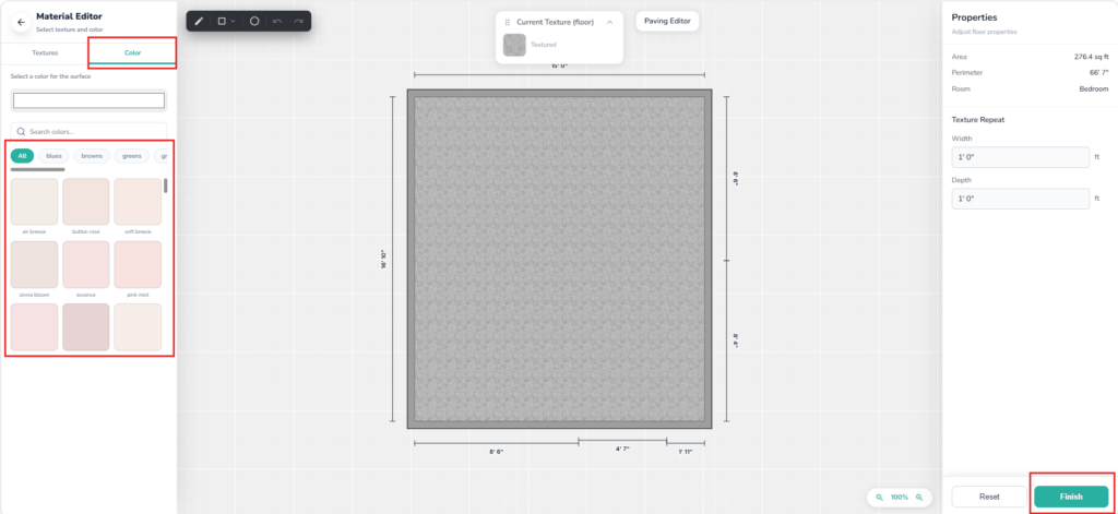
When you select an enclosed room area on your floorplan and click on the advanced Floor Editor from the floating toolbar, Zlendo Realty opens a focused drafting environment dedicated entirely to ground-surface styling and dimensional boundaries.
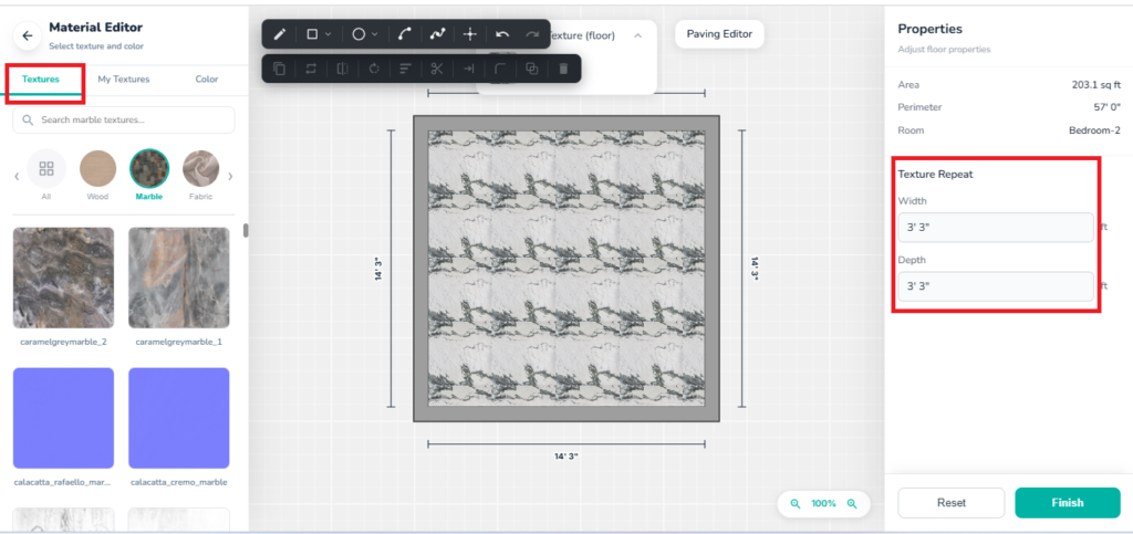
Review Spatial Metrics & Properties
Inside the Advanced editor interface, the right-hand Properties panel displays accurate architectural data calculated from your 2D floor plan:
Area: Displays the total square footage of the enclosed space (e.g., 276.4 sq ft).
Perimeter: Tracks the exact linear running distance of the room’s boundary walls.
Room: Displays the classification label assigned to the space (e.g., Bedroom, Living Room).
Browse and Select Flooring Material
Use the left sidebar repository to pick the fundamental design finish for your floor:
Textures Tab: Browse through categorized flooring materials like Wood, Marble, or Fabric. Click any material swatch to immediately fill the layout canvas preview.
Color Tab: Switch to this tab to apply a solid, uniform color tone or paint finish across the deck area.
Current Texture Indicator: Located at the top-center of the screen, this floating badge provides an instant visual reference of the active material pattern.
Refine Pattern Scaling (Texture Repeat)
To make sure large-scale materials like wood planks or stone tiles look perfectly true-to-scale, adjust the distribution parameters under the Texture Repeat section in the right-hand panel:
Width: Controls the horizontal tiling span of the texture pattern before it loops.
Depth: Controls the vertical run density of the texture layout.
Working with the Floor Paving Tool #
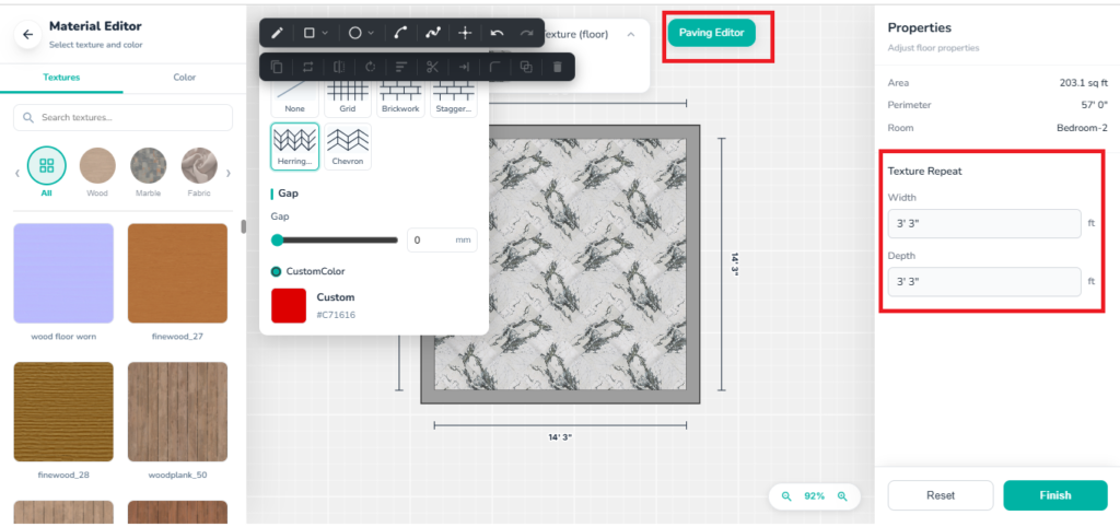
When configuring flooring designs in the Advanced Floor Editor, you can use the Paving Editor tool to overlay complex tile patterns, brick arrangements, and grout details onto your surface texture. This sub-editor, highlighted in 2.0 Floor -Adv Paving editor.jpg, lets you break away from basic uniform textures to design intricate, realistic tiled or paved layouts.
Open the Paving Sub-Menu
Locate the Paving Editor button on the top-center toolbar next to your active texture indicator.
Clicking this button opens a floating configuration panel inside the Advanced Floor Editor.
Select a Paving Pattern Matrix
Choose how your tiles or paving materials are structured by selecting one of the standard architectural pattern profiles at the top of the panel:
– None: Keeps the floor texture as a singular, unbroken material sheet.
– Grid: Aligns materials in a classic, straight stacked tile grid layout.
– Brickwork: Arranges tiles in a traditional running-bond staggered brick layout.
– Staggered: Offsets grid boundaries continuously for a modern dynamic floor flow.
– Herringbone / Chevron: Tilts and interlocks materials at precise angles—perfect for parquet hardwood flooring or premium backsplash aesthetics.
Calibrate Grout Line Gaps
Fine-tune the spaces between individual paved blocks under the Gap section of the floating panel:
Gap Slider: Drag the slider or type an exact value in millimeters (e.g., 0 mm) to shrink or expand the grout joint line widths. This gives you absolute control over tile-to-tile spacing.
Apply a Custom Grout Color
Under the Custom Color toggle, click the Custom color patch box.
This opens your palette to define the exact hex code or color value (e.g., #EFEBEB) for your grout lines, allowing you to create sharp contrast or seamless blends between your paving blocks.
Save or Reset Your Layout
Reset: Click the white button at the bottom right to discard any texture adjustments or tile alignments made during this session.
Finish: Click the green button to lock in your custom flooring design and return seamlessly to the main 2D layout workspace.
🏛️ Advanced Ceiling Editor #
The Advanced Ceiling Editor allows you to fine-tune overhead surface aesthetics, balance material distributions, and audit structural space parameters with high precision.
Changing Ceiling Textures & Colour #
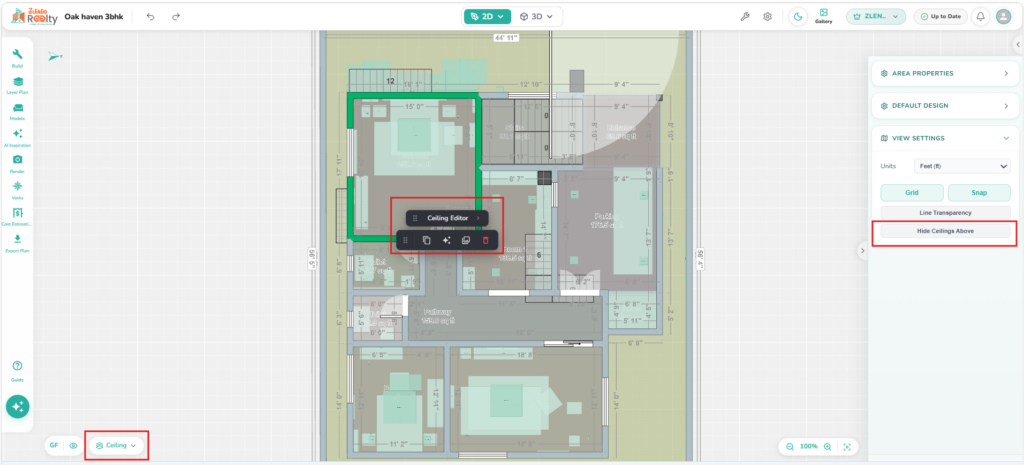
To edit a room Ceiling, select the Ceiling option in the Layers tab on the bottom-left of the main workspace. Also ensure the Hide Ceiling Above button on the right-side panel View Settings is disabled then click on the room ceiling you want to edit.
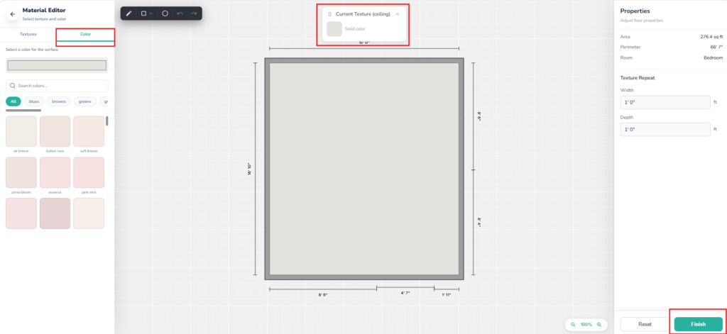
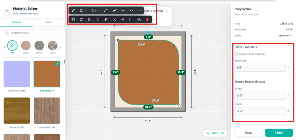
Review Spatial Metrics & Properties
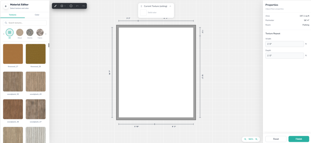
On the right side of the Advanced Ceiling editor, the Properties panel instantly populates with accurate structural metrics derived from your main floor plan:
Area: Displays the total square footage of the active ceiling surface plane (e.g., 197.1 sq ft).
Perimeter: Tracks the exact running boundary distance along the supporting walls (e.g., 56' 4").
Room: Verifies the functional classification tag of the space (e.g., Bedroom).
Select an Aesthetic Finish (Textures vs. Colors)
Use the left-hand Appearance sidebar layout visible in Ceiling editor to edit the design finish:
Textures Tab: Browse through professional categories like Wood, Marble, or Fabric. Click any pattern card (such as finewood_27 or woodplank_50) to wrap the pattern onto the canvas.
Color Tab: Switch here to pull open a custom palette for a solid, uniform paint finish.
Current Texture Indicator: Monitor the floating badge centered at the top of the workspace (Current Texture (ceiling)) to quickly audit your active selections.
Refine Pattern Scaling (Texture Repeat)
To ensure structural materials look perfectly true-to-scale across the overhead expanse, adjust the mapping constraints found under the Texture Repeat menu block:
Width: Controls the horizontal tiling span of your selected texture pattern.
Depth: Controls the vertical run density of the layout pattern.
Custom Ceiling Properties: Create and edit custom ceiling shapes using the available Draw and Modify Tools. After creating a shape, apply textures from the Material Editor and customize the appearance of each shape independently. The Shape Properties panel provides options to adjust the Thickness of the ceiling feature and configure Texture Repeat settings to control the scale and repetition of the applied texture. This allows unique ceiling designs with customized shapes, materials, and texture patterns within the same ceiling layout.
Step 4: Finalize or Revert Your Workspace Changes
Reset: Click the white button located at the lower right to drop your pending design changes and start fresh.
Finish: Click the green button at the bottom right corner of the screen to lock in your custom ceiling design and return seamlessly to your main project file.
Common Draw and Modify Tools Across Floor, Ceiling, and Wall Editors #
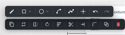
The Common Draw and Modify Tools provide a consistent set of creation and editing functions across the Floor Editor, Ceiling Editor, and Wall Editor. Use the draw tools to create geometric and freeform shapes, and the modify tools to adjust, align, duplicate, trim, extend, offset, rotate, mirror, or delete selected elements. These tools ensure precise design and editing workflows while maintaining consistency across all editor types.
Draw Tools #
Description:
The Draw Tools allow you to create custom floor shapes, boundaries, and layout guides. Use these tools to design floor areas with precise geometric shapes or freeform curves, providing flexibility for a wide range of floor planning and paving layouts.
Line: Draw straight line segments to create custom boundaries, edges, or layout guides.
Rectangle: Create rectangular floor shapes with defined width and height.
Hexagon: Draw six-sided geometric shapes for decorative or custom floor layouts.
Polygon: Create custom multi-sided shapes by defining individual corner points.
Circle: Draw perfectly circular floor areas or design elements.
Ellipse: Create oval or elongated circular shapes for custom floor designs.
Arc: Draw curved segments to create rounded edges or complex floor boundaries.
Spline: Create smooth, freeform curves by placing control points along a path.
Reference Line: Add guide lines to assist with alignment, positioning, and accurate drawing without affecting the final design.
Modify Tools #
Description:
The Modify Tools help refine and adjust existing shapes and floor elements after they have been created. Use these tools to duplicate, align, rotate, trim, extend, offset, or remove objects, enabling precise editing and efficient design modifications.
Copy: Create a duplicate of the selected shape or element.
Repeat: Generate multiple copies of the selected object at a specified spacing or pattern.
Mirror: Create a mirrored version of the selected object across a reference axis.
Rotate: Rotate the selected object around a reference point by a specified angle.
Align: Arrange objects by aligning them to a common edge, center, or reference line.
Trim: Remove unwanted portions of lines or shapes using boundary intersections.
Extend: Lengthen lines or edges until they meet another object or boundary.
Fillet Corner: Create a smooth rounded corner between two intersecting edges.
Offset: Create a parallel copy of a line or shape at a specified distance.
Delete: Remove the selected object from the design.
🪟 Advanced Materials Editor: Doors/Windows/Furniture Models #
When customizing individual objects, such as doors, windows, furniture, or decor items, clicking Material Editor on the floating action bar launches an immersive 3D styling studio.
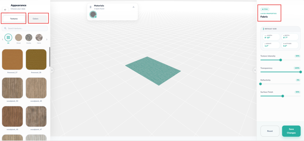
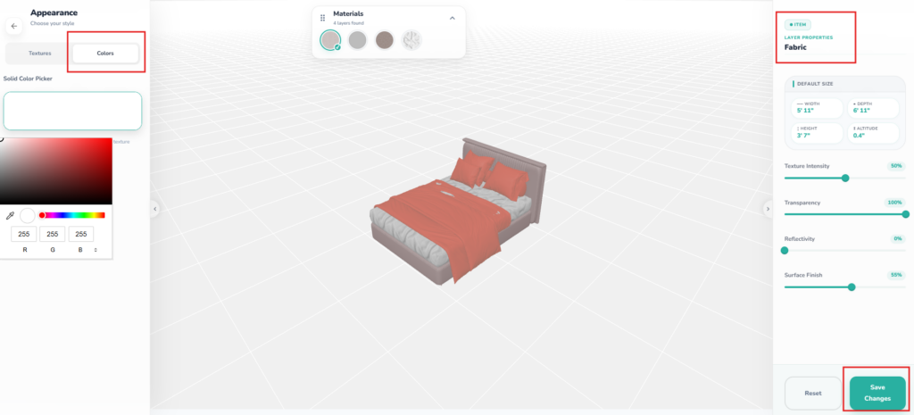
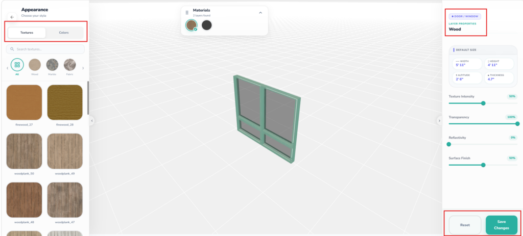
Changing an Item/Model’s Texture & Color #
The Advanced Materials editor allows you to manipulate individual component layer aesthetics, textures, and physical material finishes of furnishings and fixtures.
Identify Active Components and Layers
When a complex 3D model (like a bed) is loaded into the interface, it is broken down by its structural material properties.
Look at the top-center Materials badge to see how many independent layers or components were found on the model (e.g., 4 layers found).
The right-hand panel displays the specific Layer Property name currently selected for adjustment (e.g., Fabric, Wood, Metal).
Pick Your Styling Path (Textures vs. Colors)
Use the left-hand Appearance sidebar to select your design style:
Textures Tab: Click to apply physical textures like natural grain woods, soft woven fabrics, or polished stones to the active component layer.
Colors Tab: Open the advanced Solid Color Picker palette. You can manually drag your cursor across the color gradient box, use the rainbow hue bar, or input precise R / G / B values to apply an exact brand color matching your design palette.
Review the Model Bounding Dimensions
The right-hand panel features a read-only Default Size card that displays the absolute scale boundaries of the object as it sits in your room layout. Use this as a reference point to ensure your textures match its scale:
Width / Depth: Displays the horizontal footprint dimensions of the model.
Height / Altitude: Tracks the model’s physical vertical height and its clear height elevation off the floor plan.
Adjust Advanced Surface Properties
Fine-tune how light interacts with your applied texture or paint by adjusting the sliders in the right panel:
Texture Intensity: Controls the prominence and visual depth pop of the underlying pattern grain.
Transparency: Adjusts the alpha-opacity of the layer (set to 100% for solid, opaque objects, or lower for glass window panes and sheer fabrics).
Ref reflectivity: Determines how much environmental light bounces off the asset surface (e.g., set to higher values for glossy finishes, mirrors, or polished metals).
Surface Finish: Fine-tunes the tactile look of the material, sliding between a soft matte finish and a highly polished sheen.
Save Your Changes
Reset: Reverts the asset’s layers back to their baseline import properties.
Save Changes: Click the green button to apply the new textures, finishes, and colors directly to the model instance inside your master design file.


