Zlendo Realty Workspace comes with new features and a more efficient interface.
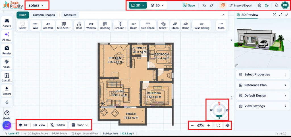
The Zlendo Workspace updates are set up to keep everything you need within reach while keeping your drawing area as clean as possible.
Editor Top Ribbon #
The workspace top Ribbon has the tools to help you control the “big picture” settings for your project.

The updated workspace top ribbon displays the following information & control buttons:
Project Name / Project Menu #
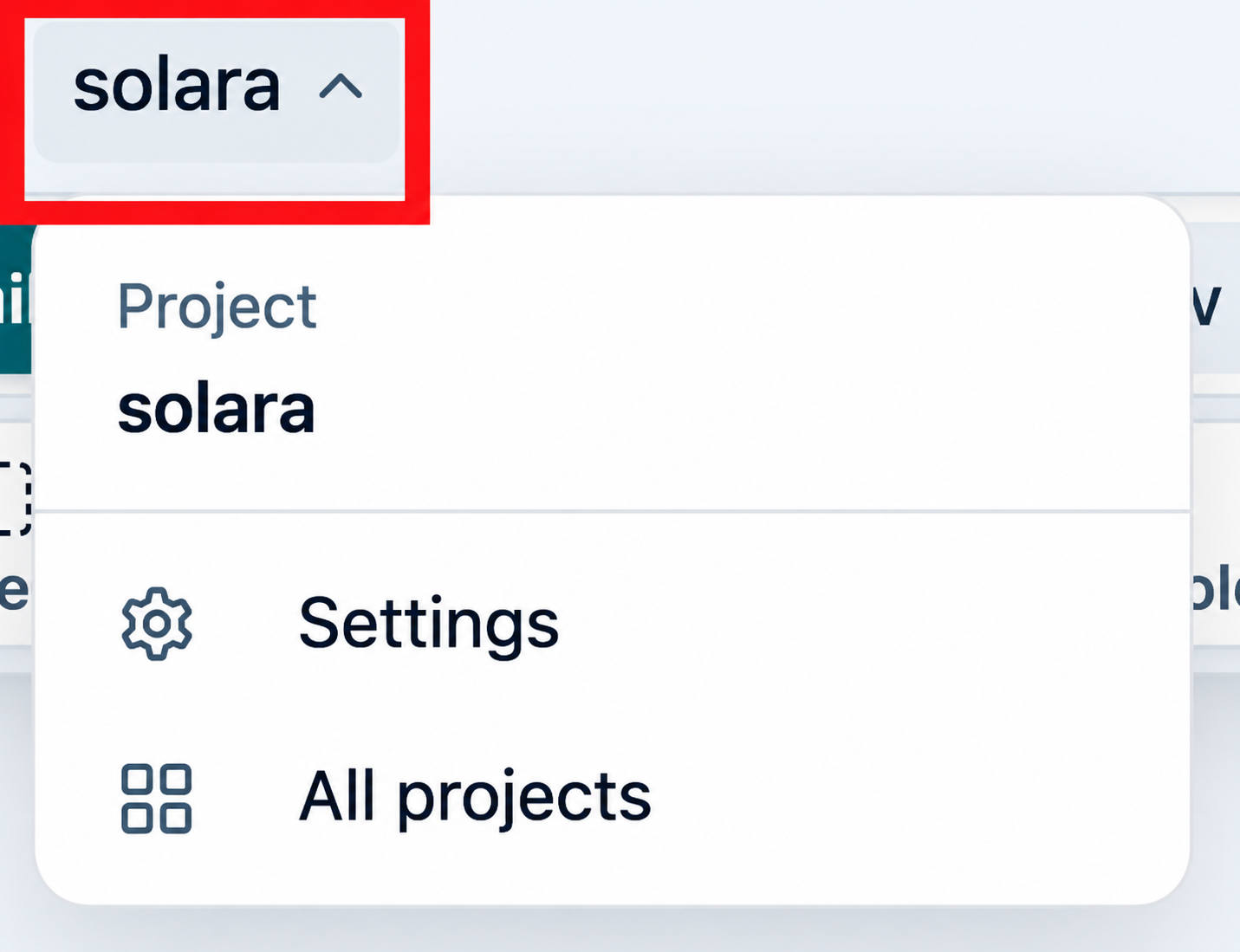
The Project Menu allows users to manage the current project and access project-related options.
Steps
- Click the Project Name drop-down (e.g., solara) located at the top-left corner of the workspace.
- The project menu opens, displaying the currently selected project.
- Click Settings to configure project-specific settings.
- Click All Projects to view and switch between available projects.
- Select the required option to continue managing the project.
2D View Mode #
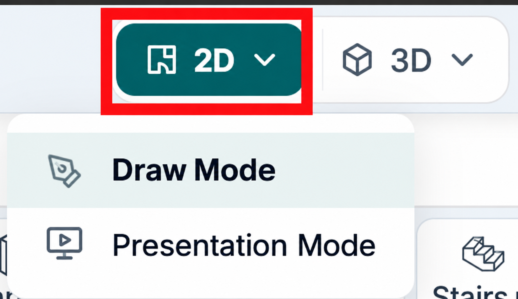
The 2D View Mode menu allows users to switch between different 2D workspace viewing options.
Steps
- Click the 2D dropdown located in the top toolbar.
- The menu displays the available 2D viewing modes.
- Select Draw Mode to create and edit floor plans and design elements.
- Select Presentation Mode to view the design in a clean presentation layout with editing tools minimized.
- The workspace updates automatically based on the selected mode.
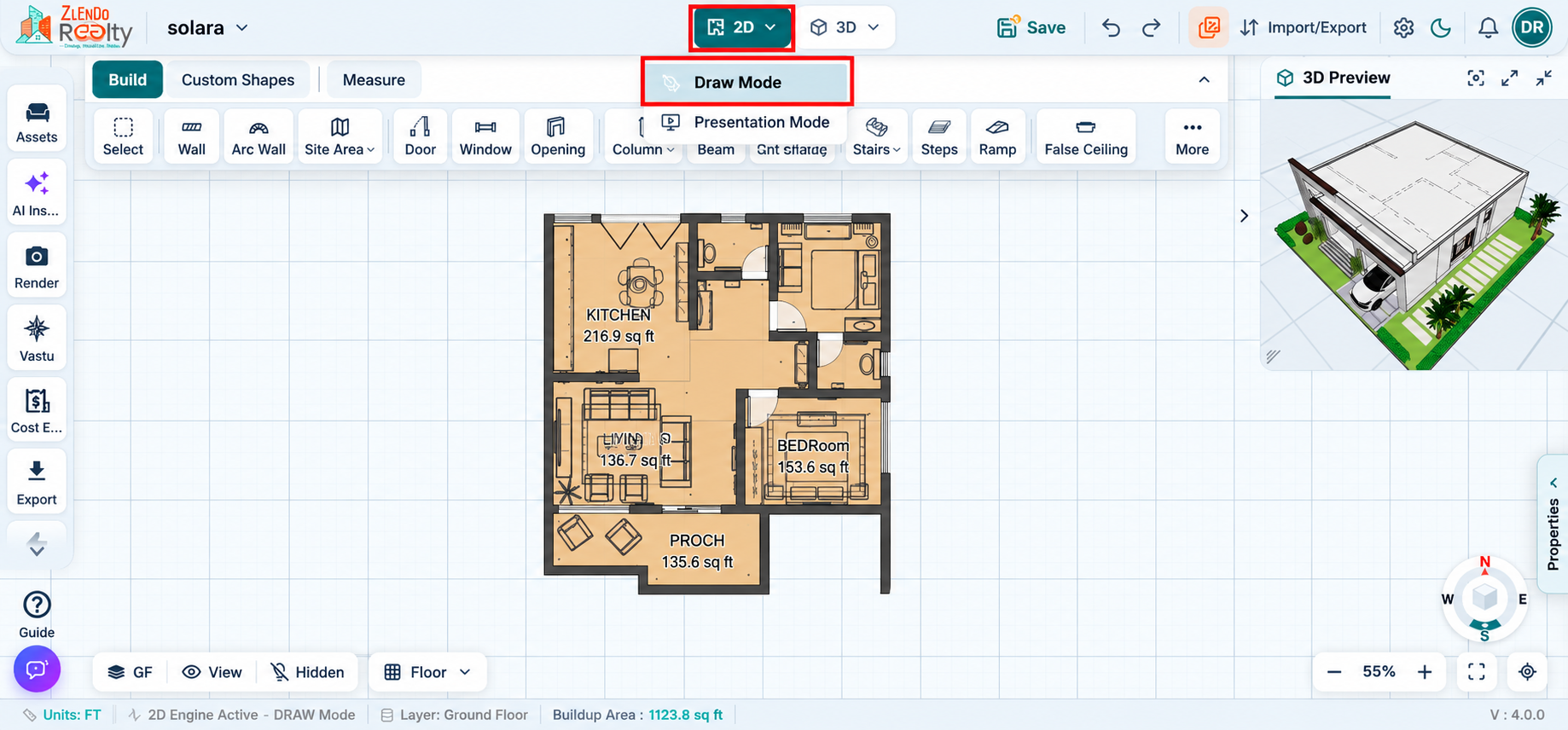
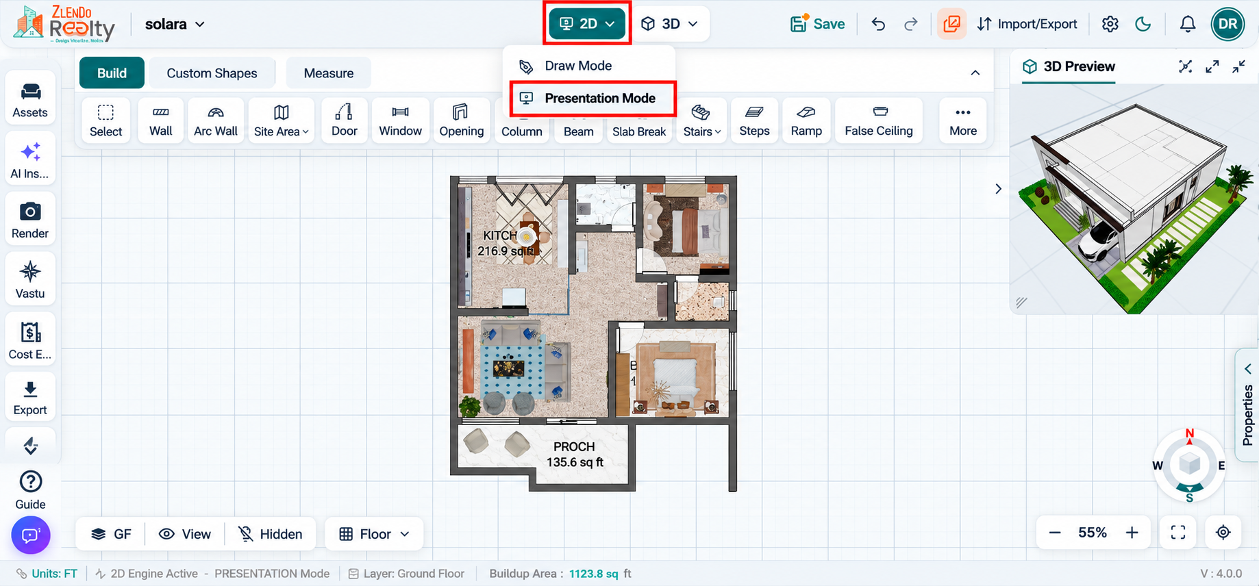
Note: Use Draw Mode for design creation and modifications, and Presentation Mode for reviewing or presenting the design with a simplified interface.
3D View Mode #
The 3D View Mode menu allows users to switch between different 3D visualization and navigation modes.
Steps
- Click the 3D dropdown located in the top toolbar.
- The menu displays the available 3D viewing modes.
- Select Edit Mode to modify design elements while viewing the model in 3D.
- Select Walk Mode to explore the design through an immersive walkthrough experience.
- The workspace automatically updates to the selected 3D mode.
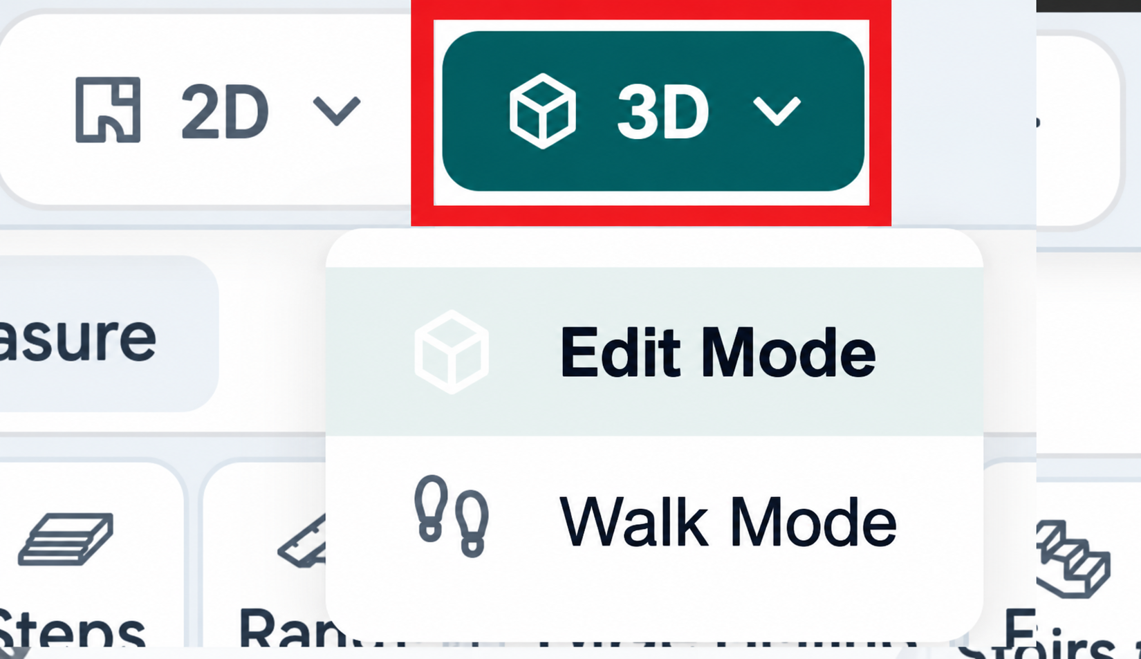
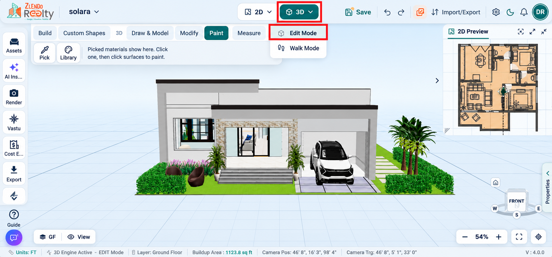
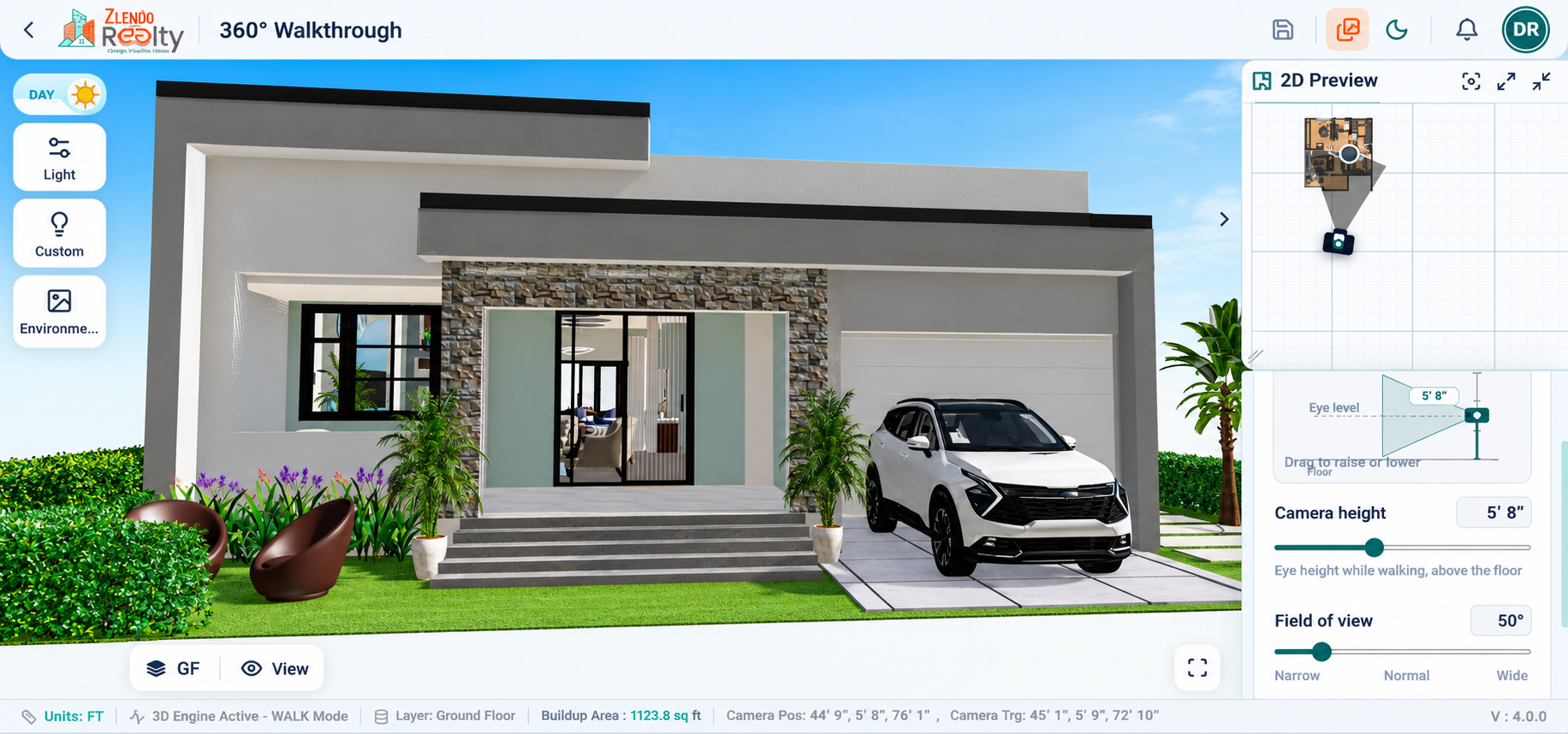
Note: Use Edit Mode when making changes to the 3D model and Walk Mode to review the design from a real-world perspective through interactive navigation.
Save #
The Save option allows users to store all recent modifications made to the project.
Steps
- Make the required changes to the design.
- Observe the notification indicating unsaved changes.
- Click the Save button located in the top toolbar.
- The application saves the current project updates.
- Continue working with the assurance that all changes have been stored successfully.
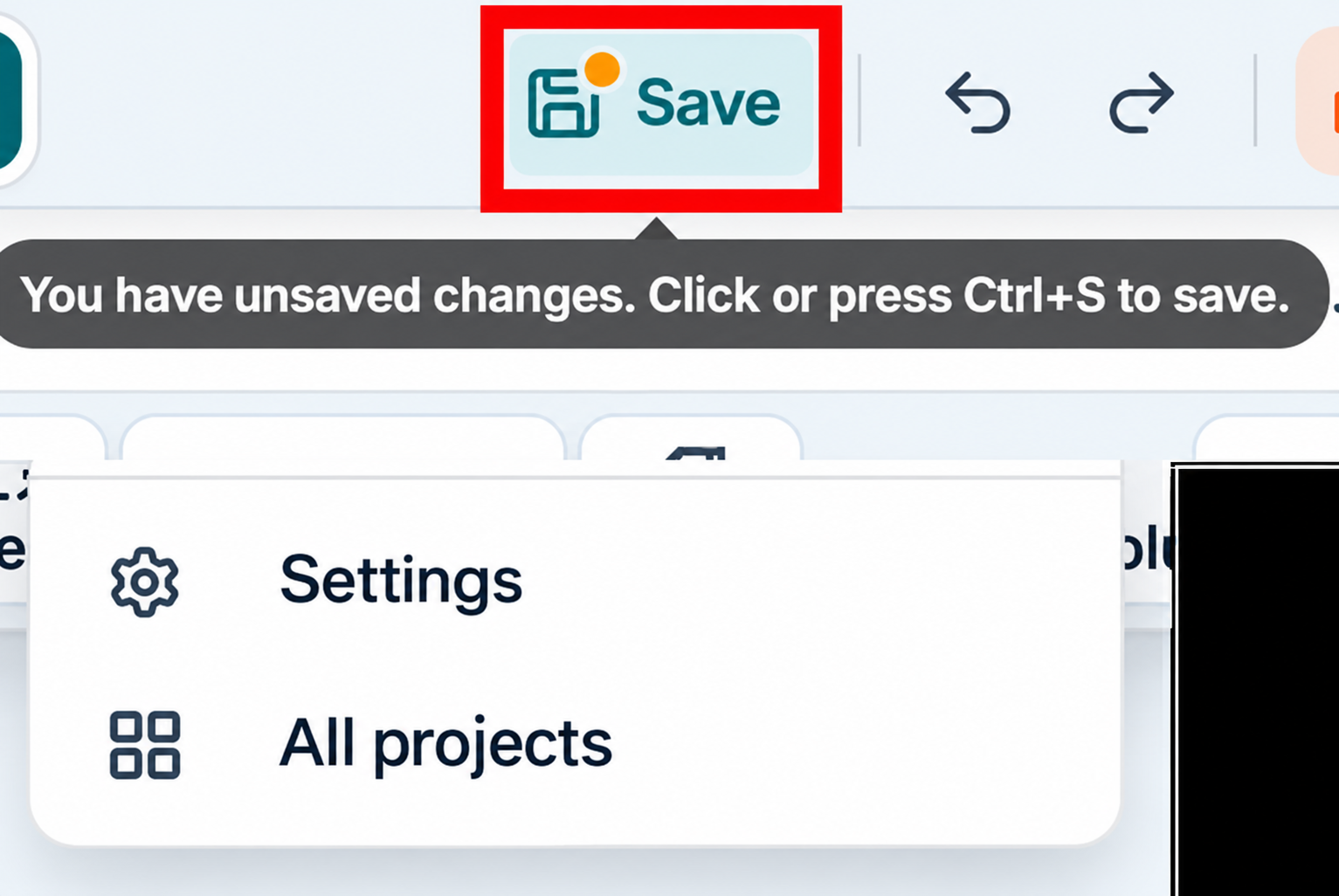
Note: When unsaved changes exist, a tooltip message appears prompting users to click Save or use the keyboard shortcut Ctrl + S to save the project.
Undo and Redo #
The Undo and Redo controls allow users to quickly reverse or restore recent actions performed within the project.
Steps
- Click Undo to reverse the most recent action.
- Continue clicking Undo to step back through previous changes.
- Click Redo to restore an action that was previously undone.
- Continue clicking Redo to reapply additional reverted actions.
- Use these controls to conveniently correct mistakes without manually recreating design changes.
Note: The Undo option removes the latest action, while Redo restores an action that was reversed using Undo. These controls help streamline the design workflow and reduce the need for manual corrections.
Gallery #
The Recent Activity Gallery provides quick access to recently generated screenshots, renders, and project visuals.
Steps
- Click the Gallery icon from the top toolbar.
- The Recent Activity panel opens, displaying recently generated project outputs.
- Browse through the available image thumbnails and render previews.
- Select a thumbnail to view the corresponding project output.
- Click View Gallery at the bottom of the panel to access the complete gallery and manage all saved visuals.
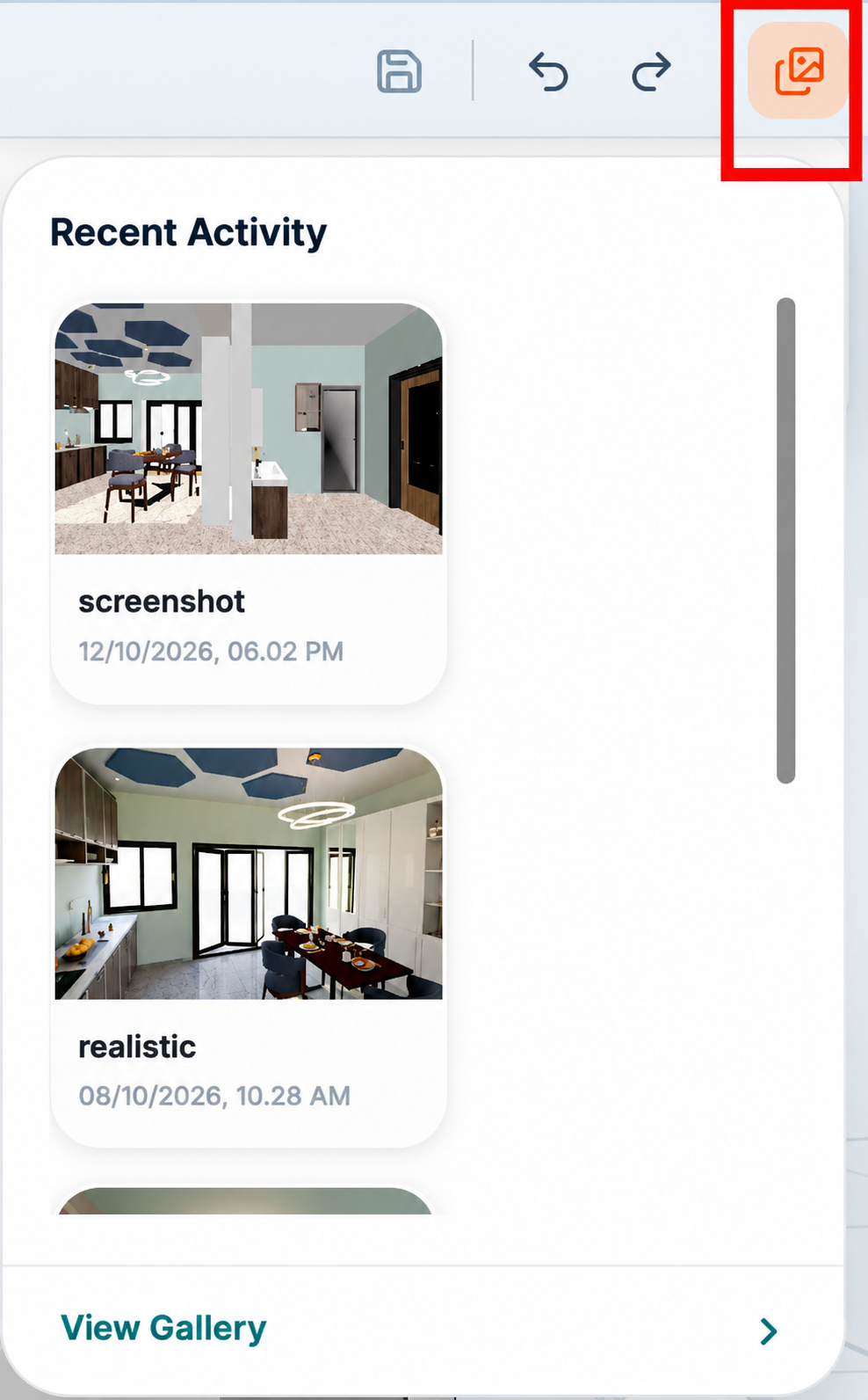
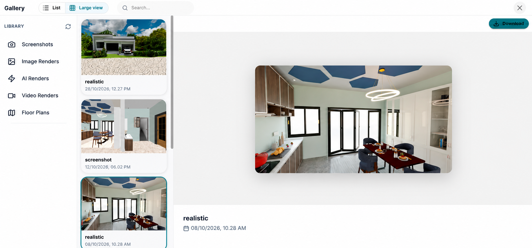
Note: The Recent Activity section displays the latest generated screenshots and rendered images, allowing users to quickly revisit and access previous project outputs.
Import/Export #
The Import/Export menu allows users to back up projects, exchange design files, and import existing project data.
Steps
- Click the Import/Export button from the top toolbar.
- The menu displays both Export and Import options.
- Under Export, select:
- Project file (.json) to download a complete backup of the current project.
- CAD / 3D formats to export the design in supported CAD and 3D file formats such as DXF or DAE.
- Under Import, select:
- Project file (.json) to load an existing project file.
- Choose the desired file and complete the import or export process.
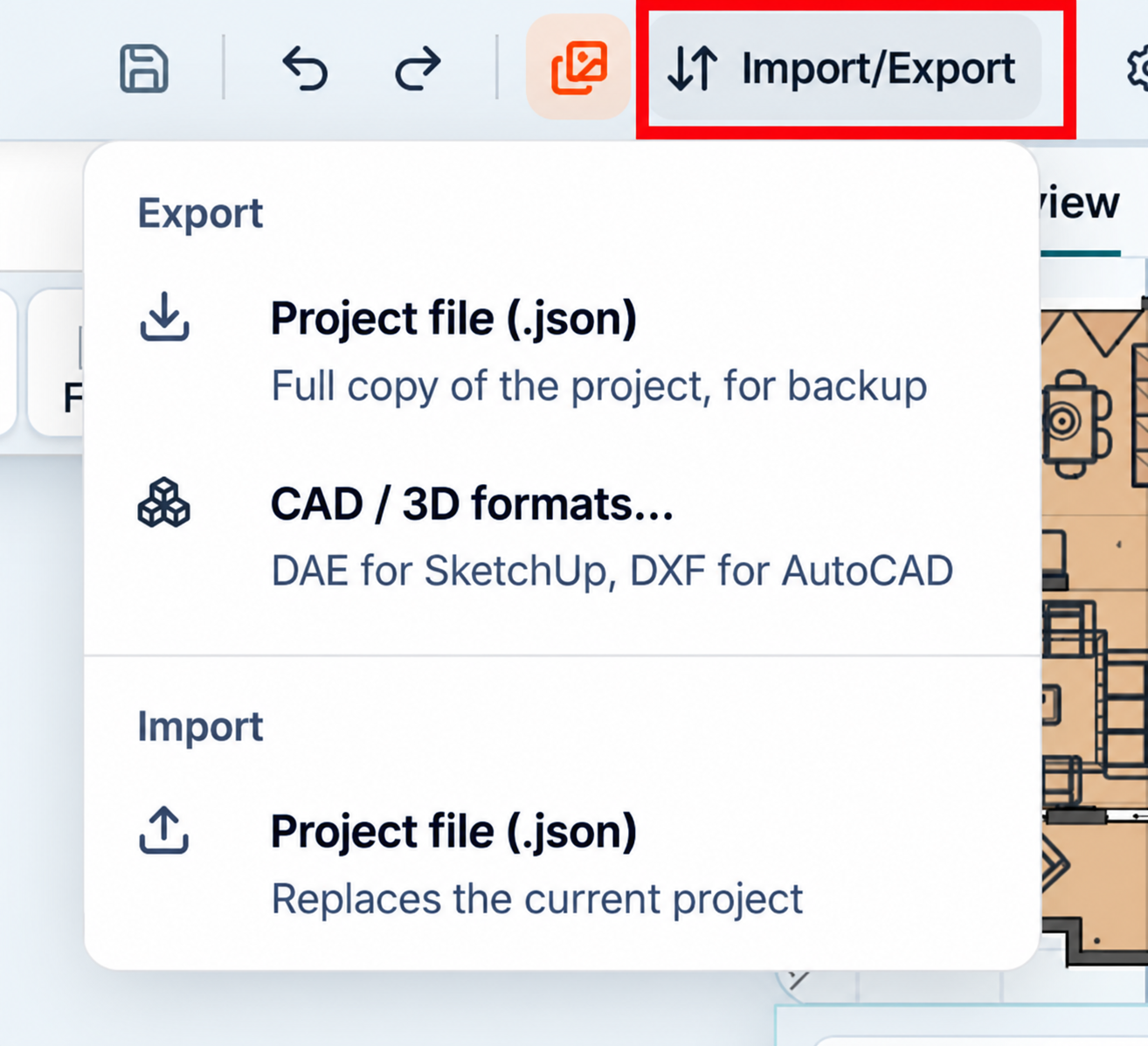
Note: Importing a Project file (.json) replaces the currently opened project, while exporting creates a backup or a shareable version of the design in the selected format.
Settings #
The Settings window provides centralized access to application preferences and workspace customization options.
Steps
- Click the Settings icon from the top toolbar.
- The Settings window opens in a full-screen dialog view.
- Select a category from the left panel:
- General – Configure units, themes, rotation angle, and floor opening visibility.
- Editor View – Control dimension and measurement display settings.
- Performance – Optimize visual quality and system responsiveness.
- Logs – View application log information.
- Modify the required settings based on project and user preferences.
- Click Done to save and apply the selected changes.
- Click the Close (X) icon to exit the Settings window without making further changes.
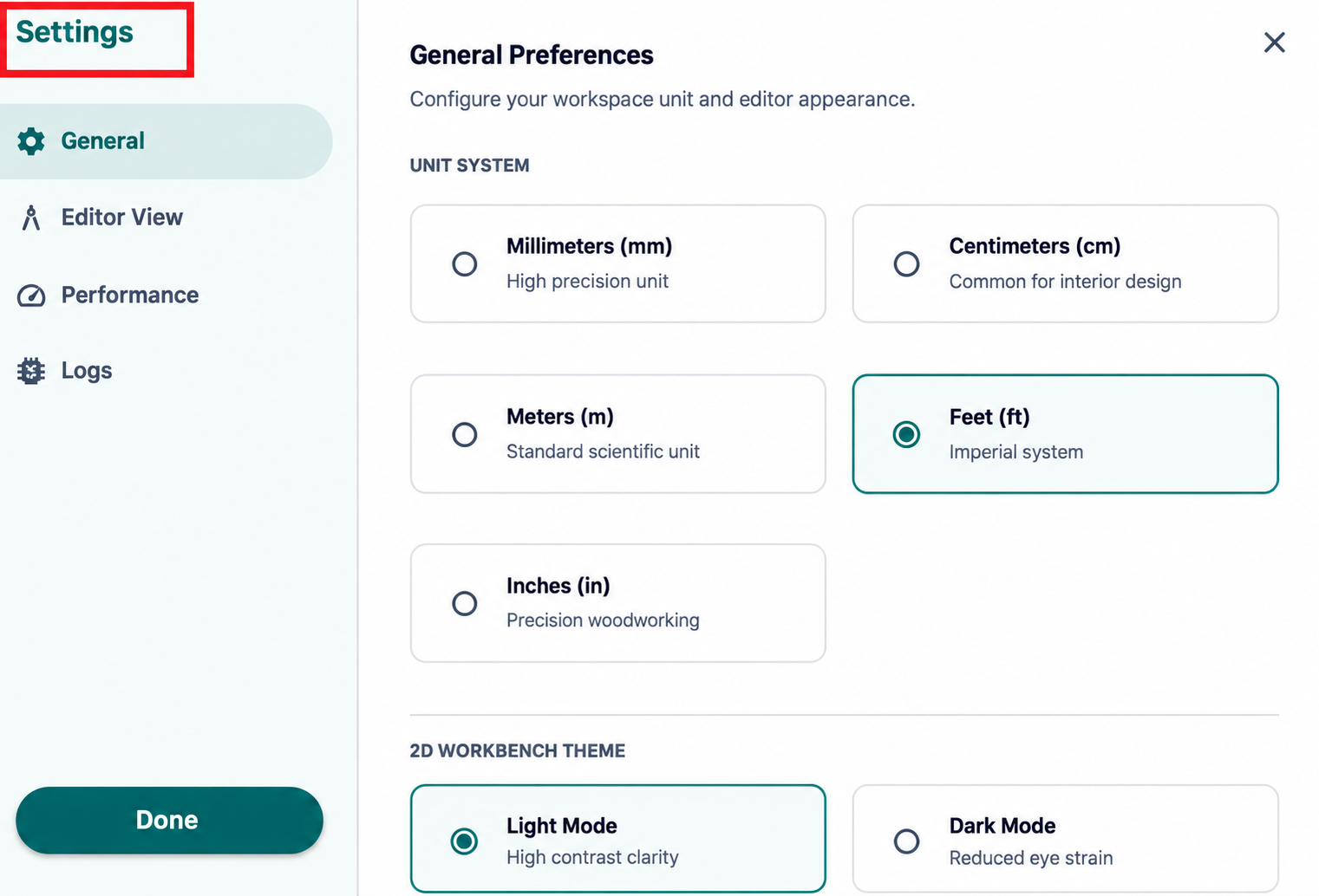
Note: All workspace, visualization, and performance-related configurations can be managed from the Settings window, providing a single location for customizing the design environment.
General Settings #
The General Settings page allows users to configure workspace preferences, measurement units, visual themes, and display options.
Steps
- Open the Settings window and select General from the left navigation panel.
- Choose the preferred Unit System for project measurements.
- Select a 2D Workbench Theme such as Light Mode or Dark Mode.
- Specify the Rotation Angle value for object rotation operations.
- Configure Floor Opening Visibility by selecting either Solid Line or Dotted Line display style.
- Click Done to save and apply the selected settings.
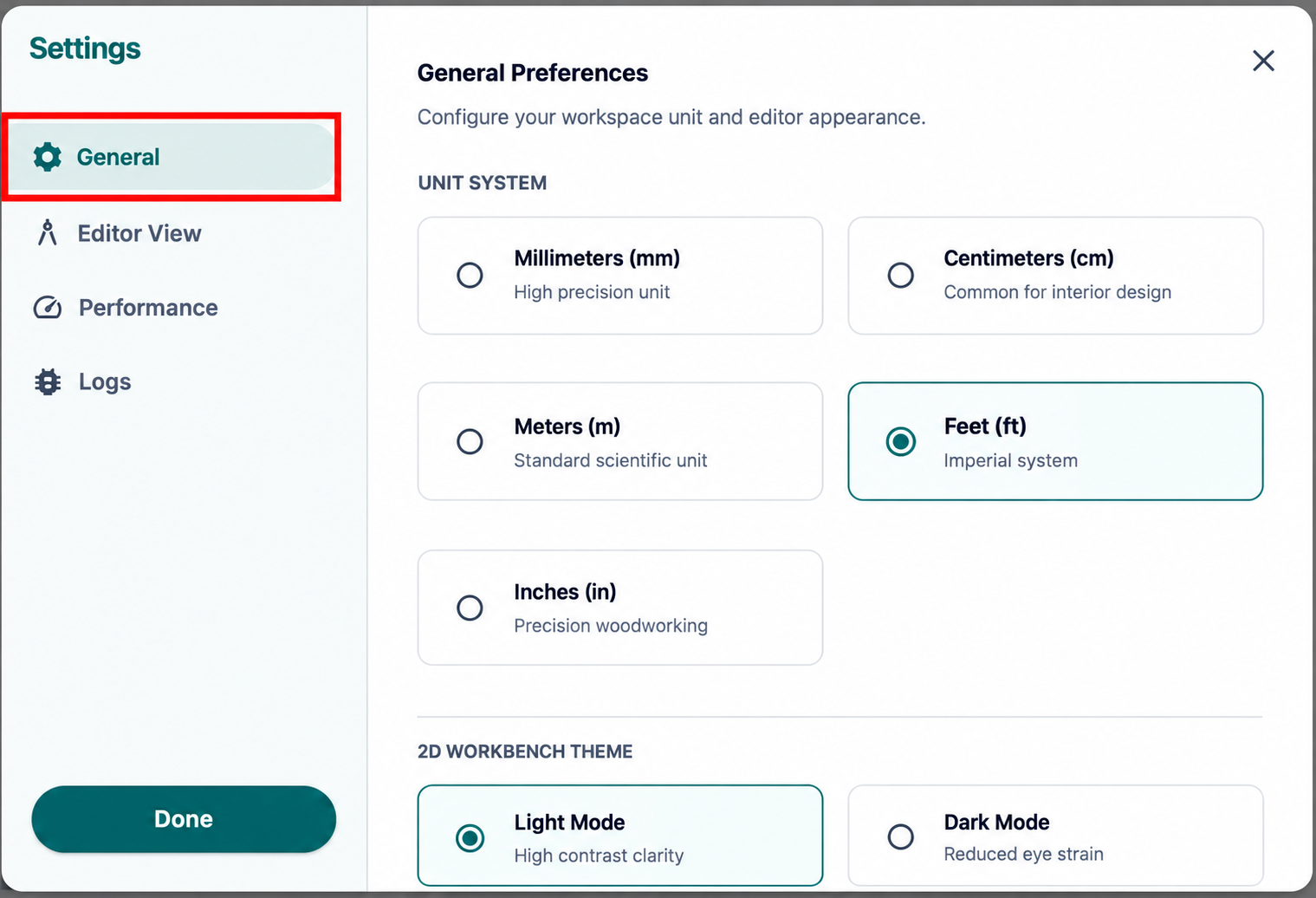
Note: The General Settings page provides essential workspace customization options that affect measurement display, editor appearance, and visual representation throughout the project.
Editor View Settings #
The Editor View settings page allows users to customize how dimensions, measurements, and visual guides are displayed within the workspace.
Steps
- Open the Settings window and select Editor View from the left navigation panel.
- Choose the preferred Dimension Visibility option:
- Inner & Outer Dimensions
- Inline Only (Inside lines)
- Outline Only (Outside lines)
- Centerline (Line-to-wall)
- Minimal Mode (Hide all)
- Select the required Area Dimension Visibility mode.
- Enable or disable Line Transparency Mode to automatically fade lines when the camera is close to them.
- Enable or disable the CAD Toolbar for quick access to CAD tools in 3D Edit Mode.
- Click Done to save and apply the selected settings.
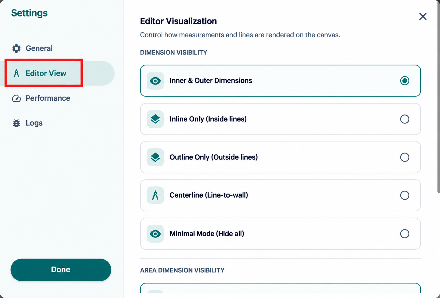
Note: Editor View settings control only the visual appearance of measurements and guides in the workspace and do not affect the actual design dimensions or geometry.
Performance Settings #
The Performance Settings page allows users to optimize the application’s performance and visual quality based on device capabilities.
Steps
- Open the Settings window and select Performance from the left navigation panel.
- Choose the desired performance mode:
- Battery Saver – Prioritizes battery life by reducing visual effects and resource usage.
- Balanced – Recommended mode that provides an optimal balance between performance and visual quality.
- High Performance – Enables enhanced graphics, lighting, and textures for maximum visual fidelity.
- Review the selected performance profile.
- Click Done to save and apply the changes.
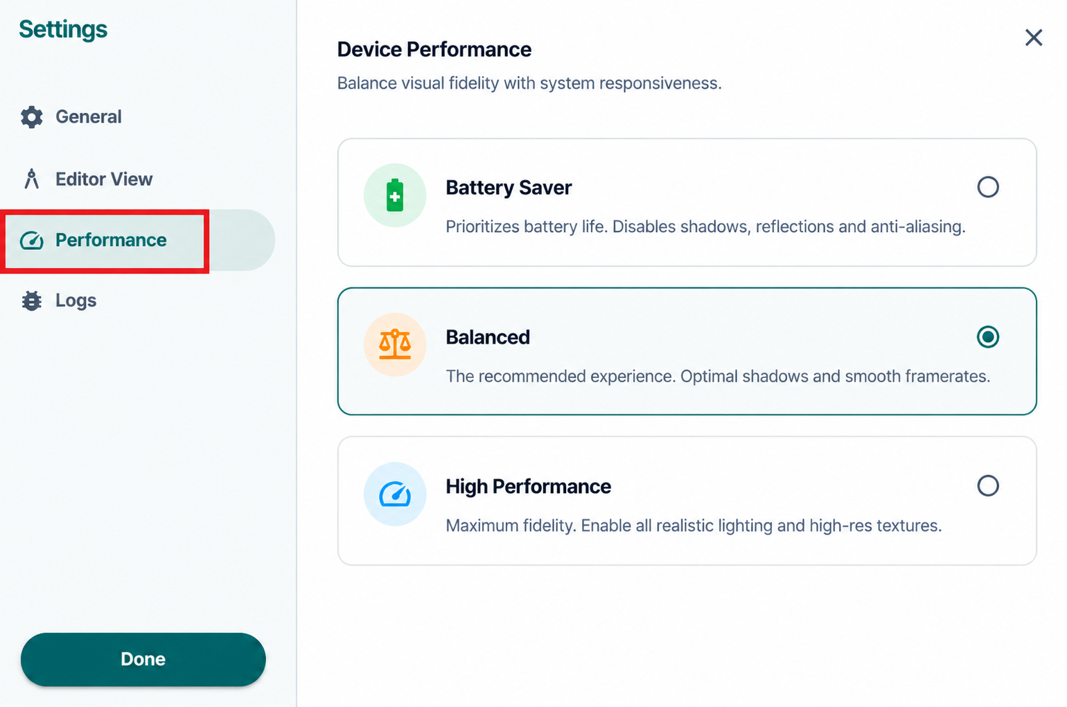
Note: Performance settings affect rendering quality, visual effects, and application responsiveness. Select the mode that best matches your device performance requirements.
Theme Mode #
The Theme Mode toggle allows users to switch the workspace appearance between light and dark themes.
Steps
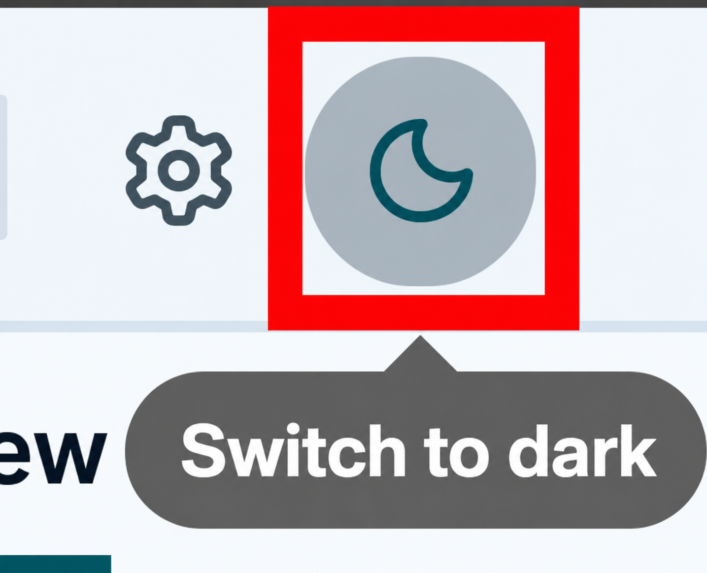
- Locate the Theme Mode button in the top toolbar.
- Hover over the button to view the current theme option.
- Click the Theme Mode button.
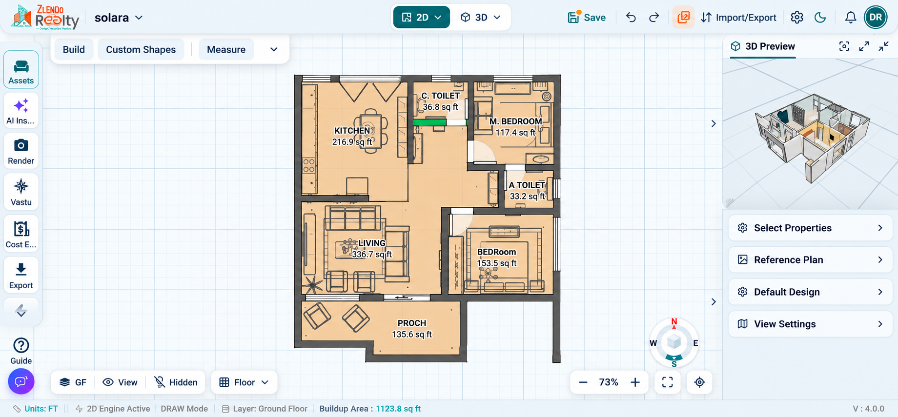
- The workspace appearance changes between Light Mode and Dark Mode.
- Continue working with the selected theme applied across the interface.
Day
Night
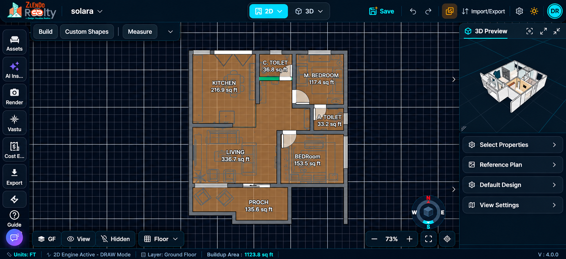
Note: Dark Mode helps reduce eye strain in low-light environments, while Light Mode provides a brighter workspace for improved visibility.
Notifications #
The Notifications panel allows users to view recent project updates, rendering progress, system alerts, and other application notifications.
Steps
- Click the Notification bell icon located in the top toolbar.
- The Notifications panel opens and displays recent activity and alerts.
- Review the list of notifications, including rendering completion messages and project updates.
- Click Mark all as read to clear unread notification indicators.
- Click View older notifications to access previous notification history.
- Close the panel to return to the workspace.
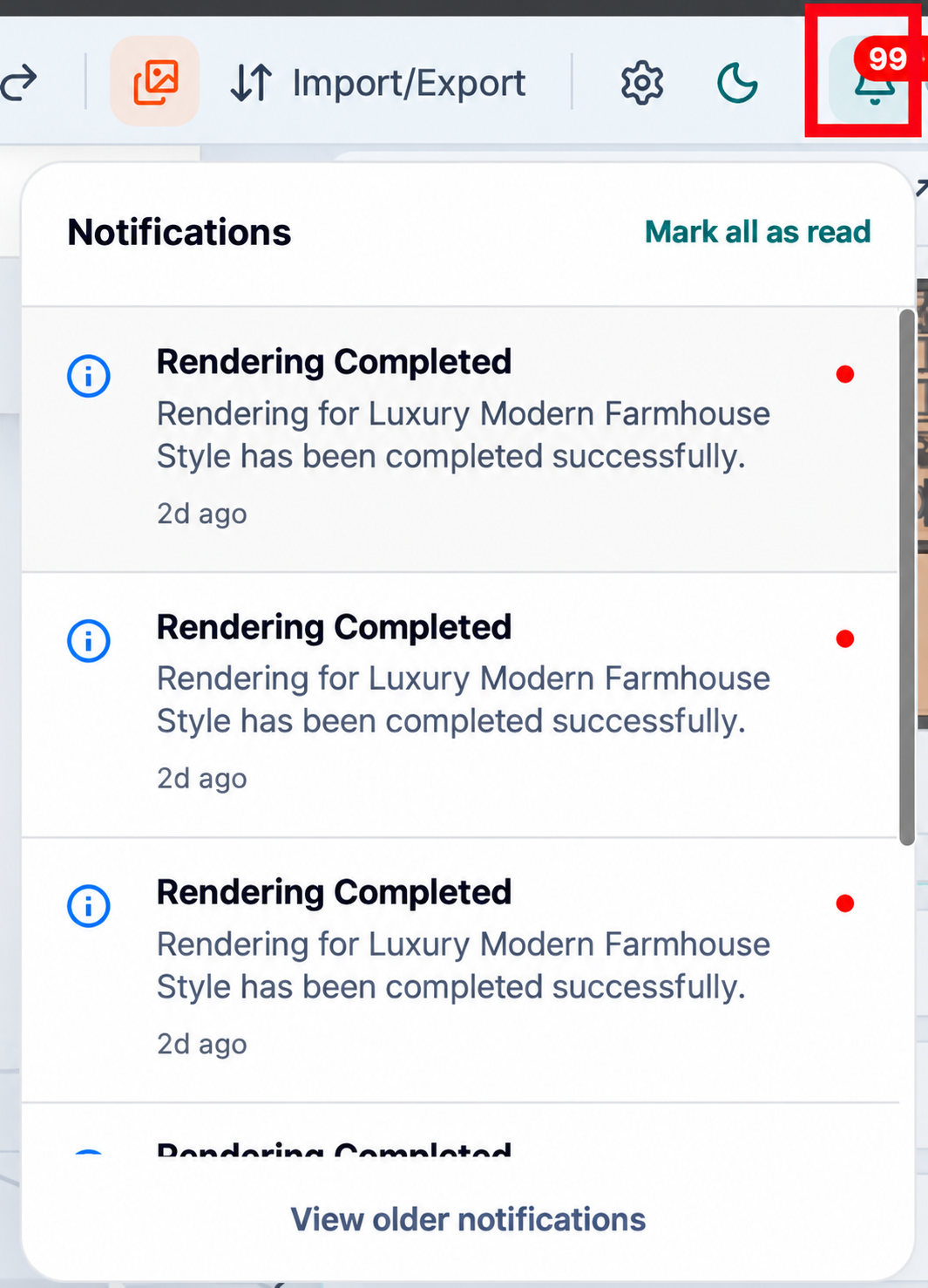
Note: Unread notifications are indicated by a red dot, helping users quickly identify new project updates and completed background processes such as renderings.
User Profile #
The User Profile panel provides access to account information, subscription details, and user-related actions.
Steps
- Click the Profile icon located in the top-right corner of the toolbar.
- The User Profile panel opens and displays account details.
- Review the registered email address and active workspace information.
- View the current subscription or plan details.
- Use the available account options as needed.
- Click Exit Tool to leave the application.
- Close the panel to return to the workspace.
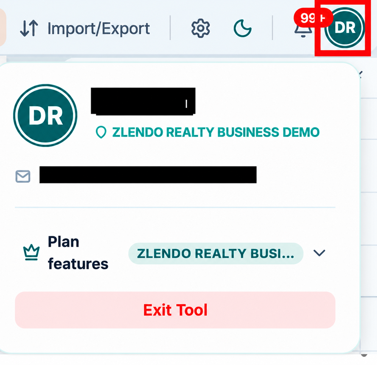
Note: The User Profile panel allows users to quickly access account information and manage profile-related settings from a single location.
2D Build toolbar #
The Build toolbar in 2D View provides essential architectural drafting tools used to create and modify structural elements within a floor plan.

Steps
- Switch to 2D View and select the Build tab.
- Choose the required building tool from the toolbar.
- Available tools include:
- Select – Select and modify design elements.
- Wall / Arc Wall – Create straight or curved walls.
- Site Area – Define the project boundary or site area.
- Door / Window – Add doors and windows to walls.
- Opening – Create wall openings.
- Column / Beam – Insert structural elements.
- Sun Shade – Add shading structures.
- Stairs / Steps / Ramp – Create vertical circulation elements.
- False Ceiling – Design ceiling layouts.
- More – Access additional building tools.
- Click within the workspace to place or draw the selected element.
- Modify the element properties as required.
Note: The Build toolbar contains all primary construction and architectural components required for creating a complete floor plan in the 2D workspace.
2D View Custom Shapes toolbar #
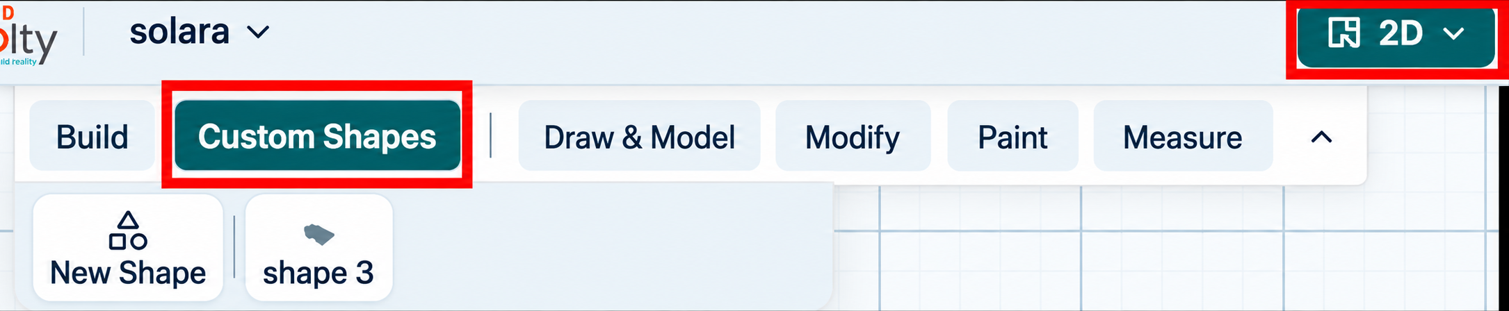
The Custom Shapes toolbar in 2D View allows users to create and place predefined custom shapes within the design workspace.
Steps
- Switch to 2D View from the top toolbar.
- Click the Custom Shapes tab.
- The available custom shape options are displayed.
- Select the required shape, such as New Shape or an existing custom shape template.
- Click in the workspace to place the selected shape.
- Adjust the shape size and position as needed.
Note: The Custom Shapes toolbar provides quick access to reusable geometric layouts, helping users create complex floor plan elements more efficiently.
2D View Measure toolbar #
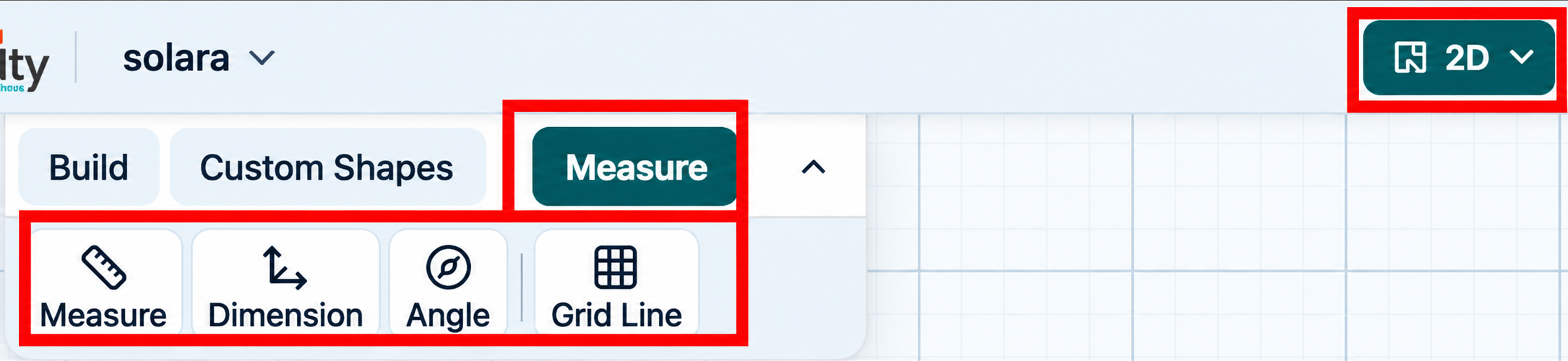
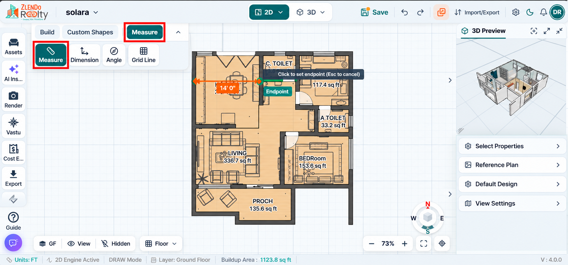
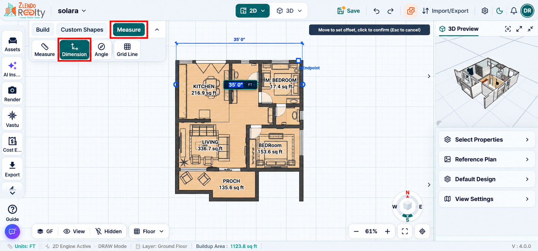
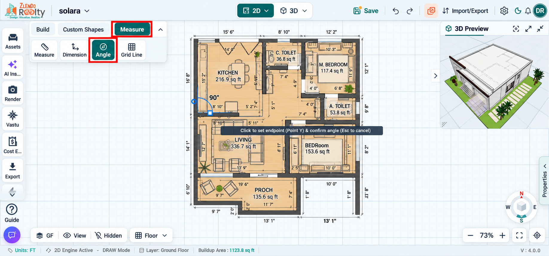
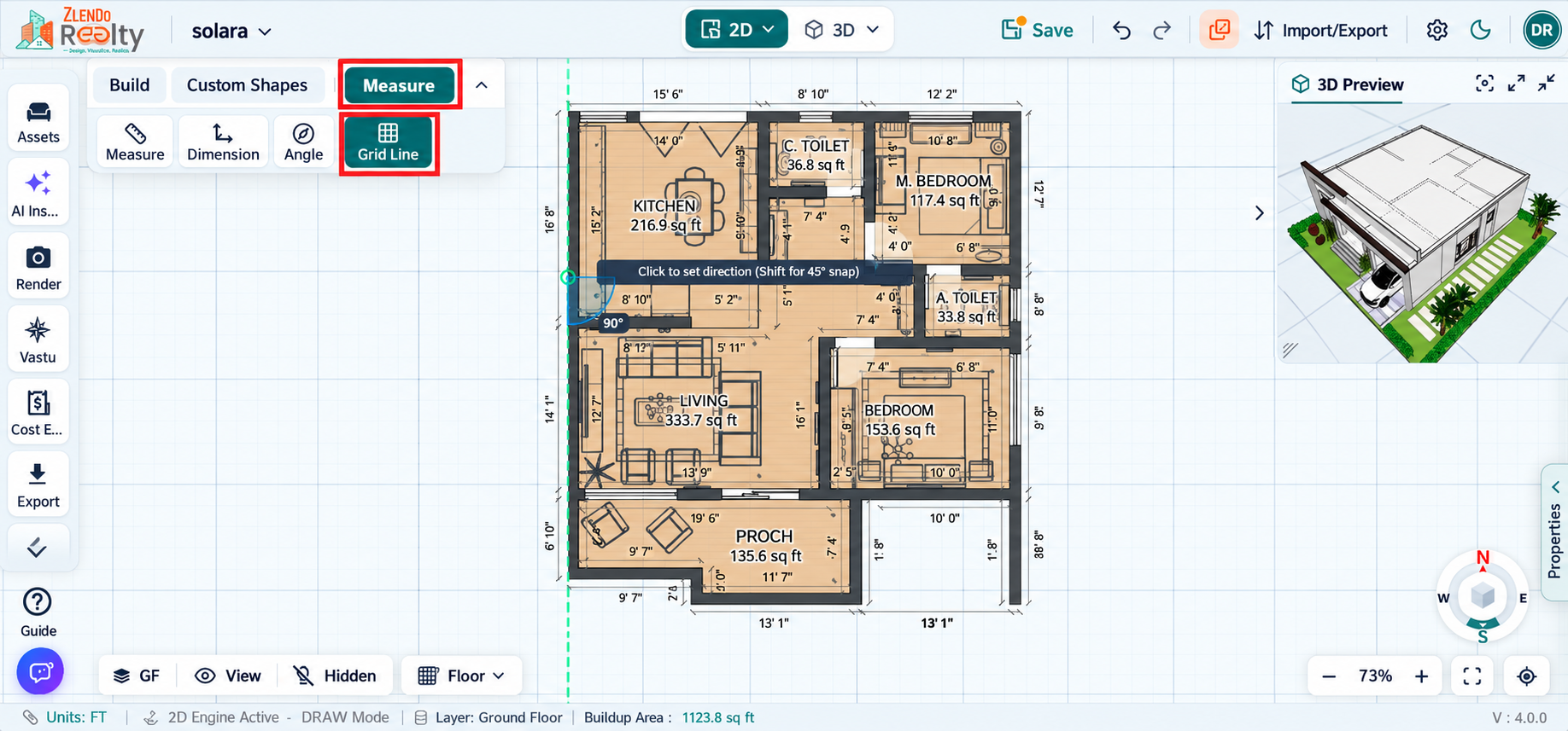
The Measure toolbar in 2D View provides tools for creating measurements, dimensions, angles, and grid references within the floor plan.
Steps
- Switch to 2D View from the top toolbar.
- Click the Measure tab.
- Select the required measurement tool:
- Measure – Calculate distances between points.
- Dimension – Add dimension annotations to objects and layouts.
- Angle – Measure and display angles between lines or elements.
- Grid Line – Create reference grid lines for accurate design alignment.
- Click within the workspace to place the selected measurement or guide.
- Adjust and position the measurement elements as required.
Note: The Measure toolbar helps improve design accuracy by providing measurement, dimensioning, and alignment tools within the 2D workspace.
3D View Build toolbar #
The Build toolbar in 3D View provides essential tools for creating, placing, and modifying architectural elements directly within the 3D workspace.

Steps
- Switch to 3D View from the top toolbar.
- Select the Build tab.
- Choose the required building element from the toolbar:
- Select – Select and edit objects.
- Door – Add doors to the model.
- Window – Insert windows into walls.
- Opening – Create wall openings.
- Column – Place structural columns.
- Beam – Add beams to the structure.
- Sun Shade – Insert shading elements.
- Stairs – Create staircases.
- Steps – Add individual steps.
- Ramp – Create accessibility ramps.
- False Ceiling – Design ceiling layouts.
- Floor Opening – Create floor cutouts and openings.
- Flue – Add flue or duct elements.
- More – Access additional building tools.
- Click within the workspace to place or draw the selected element.
- Adjust the element properties and position as required.
Note: The Build toolbar contains the primary architectural and structural modeling tools required to create and edit building components in the 3D workspace.
3D View Custom Shapes toolbar #
The Custom Shapes toolbar in 3D View allows users to create, manage, and place predefined custom shapes within the 3D design workspace.
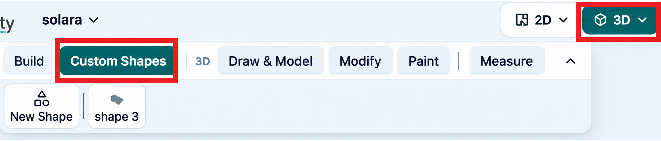
Steps
- Switch to 3D View from the top toolbar.
- Click the Custom Shapes tab.
- The available custom shape options are displayed.
- Select a custom shape, such as New Shape or an existing saved shape.
- Place the selected shape in the workspace.
- Modify the shape’s size, position, or properties as needed.
Note: The Custom Shapes toolbar helps users quickly reuse and insert predefined design elements, improving modeling efficiency and consistency across projects.
3D View Draw & Model toolbar #
The Draw & Model toolbar in 3D View provides tools for creating sketches, geometric shapes, and 3D solid models within the workspace.
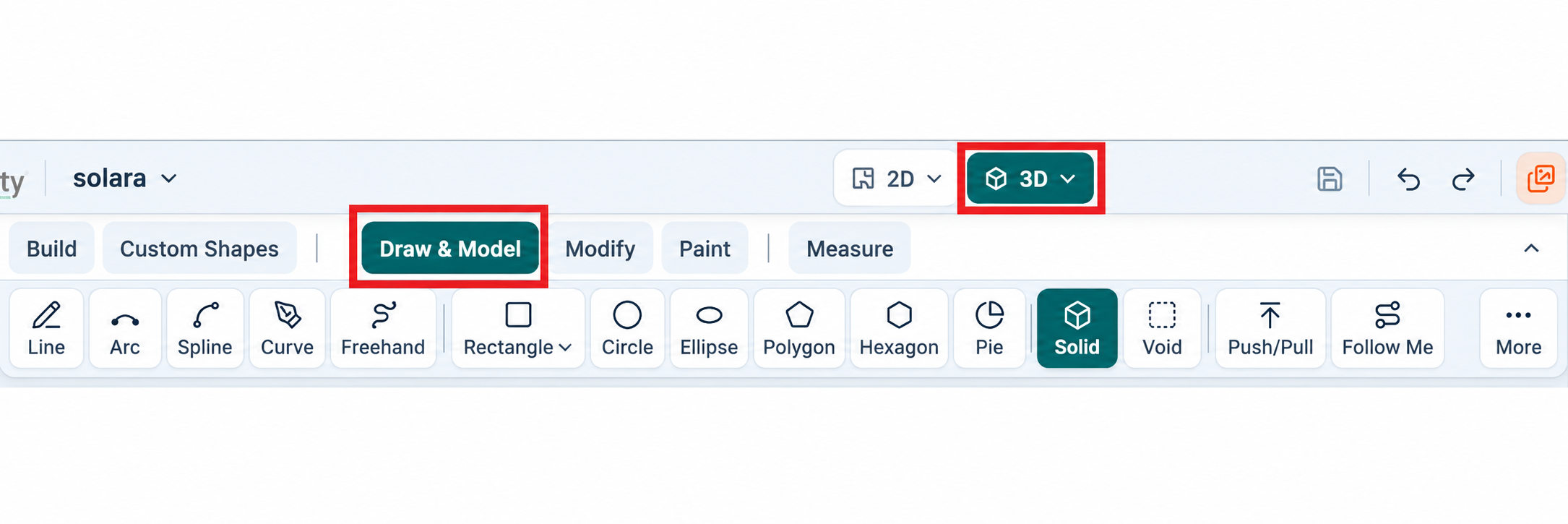
Steps
- Switch to 3D View and select the Draw & Model tab.
- Choose a drawing or modeling tool from the toolbar.
- Available tools include:
- Line – Draw straight lines.
- Arc – Create curved arcs.
- Spline – Draw smooth curves through multiple points.
- Curve – Create custom curved shapes.
- Freehand – Sketch freely in the workspace.
- Rectangle, Circle, Ellipse – Create basic geometric shapes.
- Polygon, Hexagon, Pie – Create predefined polygonal shapes.
- Solid – Generate solid 3D geometry.
- Void – Create cutouts or empty spaces within solids.
- Push/Pull – Extrude or recess surfaces to create 3D forms.
- Follow Me – Extrude a profile along a selected path.
- Draw or place the selected geometry in the workspace.
- Modify the created shape as required to complete the design.
Note: The Draw & Model toolbar is used for sketching, creating geometric forms, and transforming 2D shapes into detailed 3D models.
3D View Modify toolbar #
The Modify toolbar in 3D View provides tools for editing, transforming, and refining model geometry within the workspace.

Steps
- Switch to 3D View and select the Modify tab.
- Choose the required modification tool from the toolbar.
- Available tools include:
- Edit Nodes – Modify vertices and control points.
- Move – Reposition selected objects.
- Rotate – Rotate objects around a selected axis.
- Copy – Create duplicates of selected elements.
- Offset – Generate parallel geometry at a specified distance.
- Mirror – Create mirrored copies of objects.
- Align – Align elements relative to other objects.
- Array – Create multiple copies in a pattern.
- Join – Combine selected geometry.
- Trim – Remove unwanted portions of geometry.
- Extend – Extend geometry to meet another object.
- Fillet – Create rounded corners or edges.
- Fillet Joint – Smoothly connect intersecting elements.
- Eraser – Remove selected geometry.
- Select the object or geometry to modify.
- Apply the desired modification and adjust parameters as needed.
Note: The Modify toolbar provides powerful editing tools that help refine, adjust, and optimize 3D models without recreating geometry from scratch.
3D View Paint toolbar #
The Paint toolbar in 3D View allows users to select, manage, and apply materials to model surfaces for realistic visualization.

Steps
- Switch to 3D View and select the Paint tab.
- Click Pick to select a material from an existing surface in the model.
- Click Library to browse available materials, colors, textures, and finishes.
- Select the desired material from the library.
- Click on the target surface to apply the selected material.
- Repeat the process to paint additional surfaces as required.
Note: The Paint toolbar helps enhance the visual appearance of the model by applying realistic materials and finishes to walls, floors, ceilings, and other design elements.
3D View Measure toolbar #
The Measure toolbar in 3D View provides tools for creating measurements, angle references, and guide lines to support accurate modeling and alignment.

Steps
- Switch to 3D View and select the Measure tab.
- Choose the required measurement or guide tool from the toolbar.
- Available tools include:
- Measure – Measure distances between points and objects.
- Tape Measure – Create temporary measurement references and guide points.
- Protractor – Measure and define angles between elements.
- Grid Line – Add alignment guides within the workspace.
- Hide Guides – Temporarily hide all visible guide lines.
- Delete Guides – Remove existing guide lines from the model.
- Click within the workspace to place or use the selected tool.
- Review the generated measurements or guides and adjust as needed.
Note: The Measure toolbar helps improve modeling precision by providing measurement, angle, and guide management tools for accurate object placement and alignment in the 3D workspace.
Left-side navigation menu #
The left side bar has all the design and build tools to create a functional floorplan. The new improved version has a touch of genius added for better detailing and output.
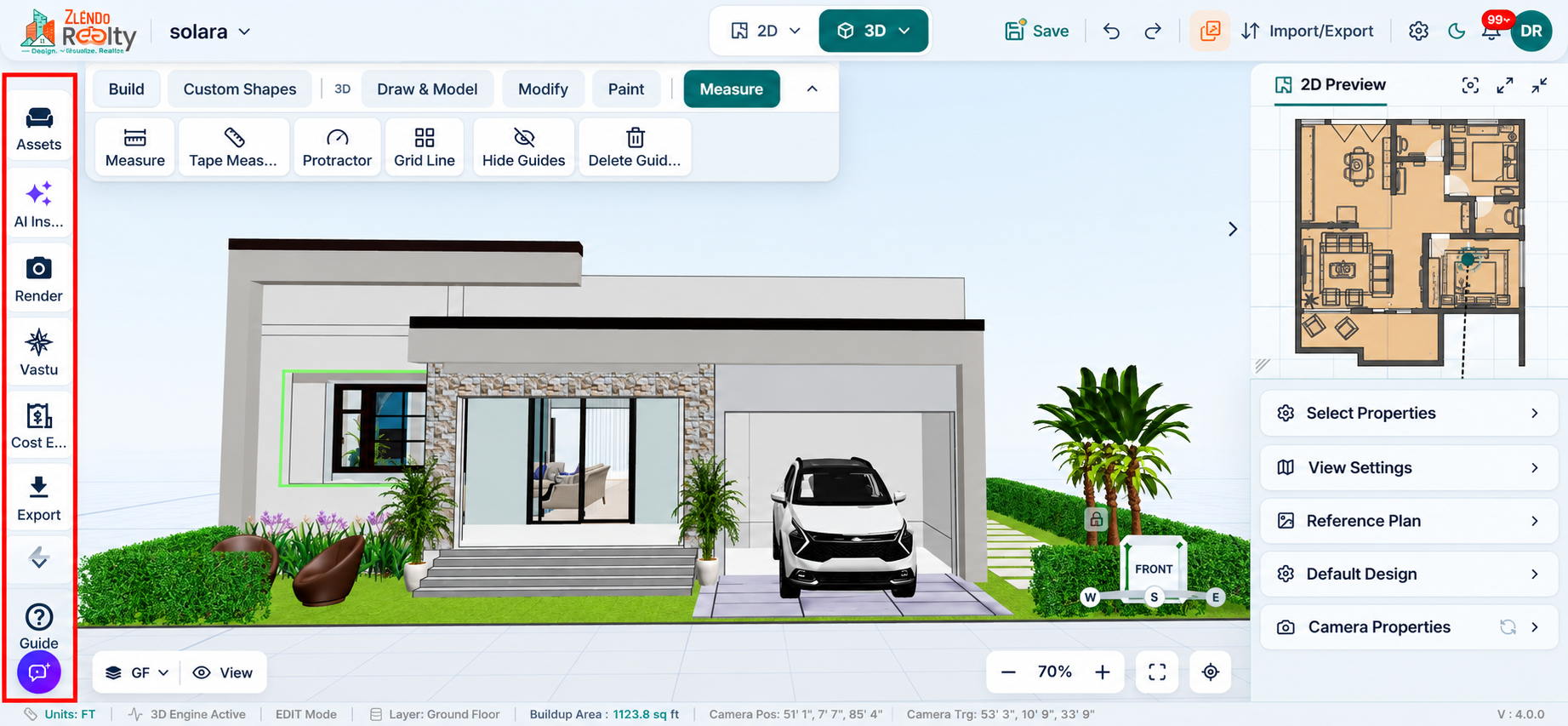
Design Tools #
Build Tool (structural elements) for your drawing board.
Layer Plan: Add / duplicate, and manage additional floors
Models (furniture/assets)
AI & Intelligence Tools #
AI Inspiration for room interior design concepts. Select a room for AI inspired interior design options.
Vastu report for checking spatial alignment and Vastu compliance of your floorplan.
Project Output Tools #
Render tool for high-quality visuals for client presentations or reports.
Cost Estimation tool for detailed project budgeting based on the location and materials chosen for your floorplan.
MEP tools provide access to Electrical, Plumbing, and Structural Diagram Editors for creating and managing building service layouts and structural plans.
Export Plan tool for generating final documentation
Support Tools #
Help Centre and quick access to drawing tutorials
Steps
- Locate the Left-Side Navigation Menu in the workspace.
- Select the required tool based on your workflow.
- Available options include:
- Assets – Browse and place design assets into the project.
- AI Inspiration – Generate design ideas and recommendations.
- Render – Create high-quality rendered images of the design.
- Vastu – Analyze the design based on Vastu principles.
- Cost Estimation – Review estimated project costs.
- Export – Export project files and outputs.
- Guide – Access help documentation and usage guidance.
- Feedback – Submit feedback and suggestions.
- Click the desired option to open its corresponding panel or tool.
- Continue working within the selected feature to manage and enhance the project.
Note: The Left-Side Navigation Menu serves as a centralized hub for accessing project resources, visualization tools, analysis features, and export functionality throughout the design workflow.
Work space Bottom #
Status bar at the bottom #
The Status Bar provides real-time information about the current project, workspace state, and camera details.
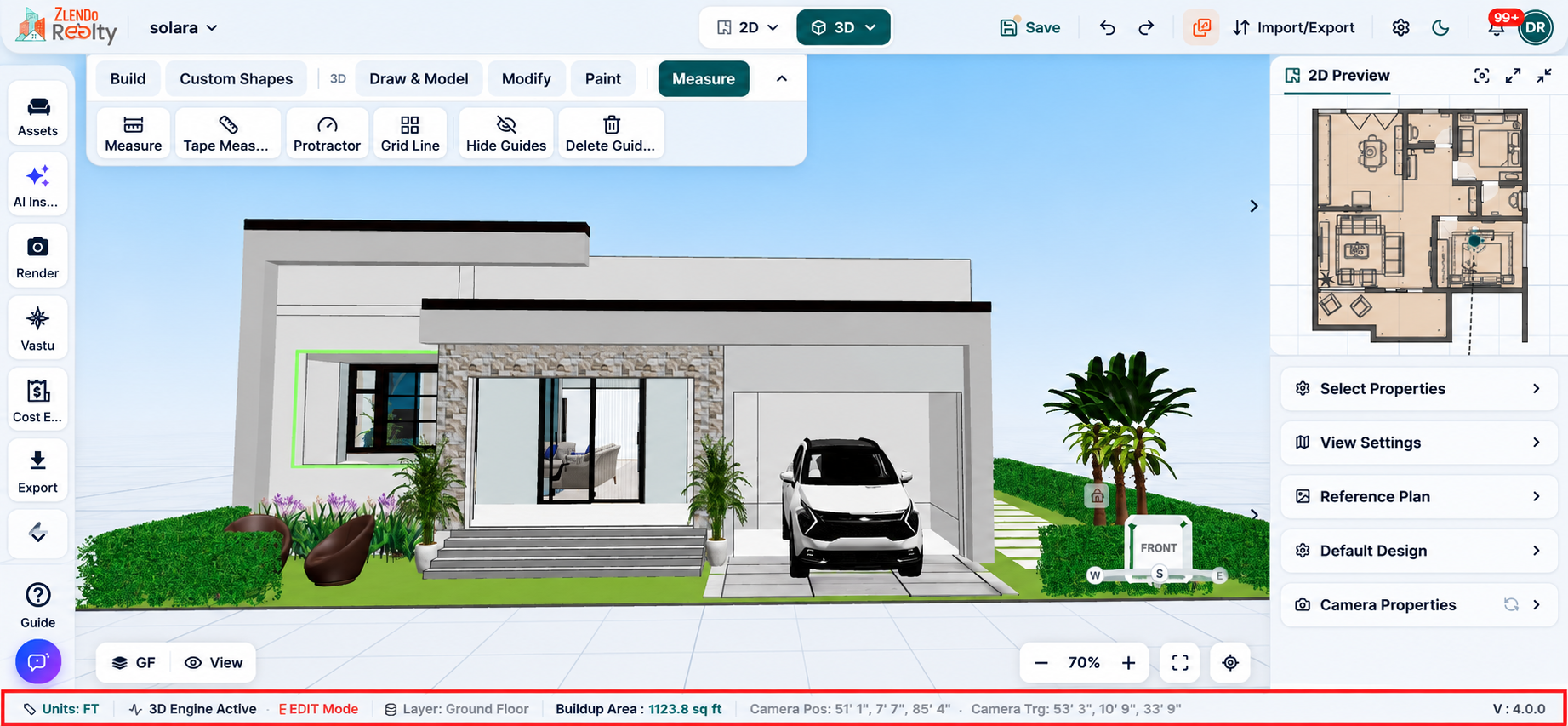
Steps
- View the Status Bar located at the bottom of the workspace.
- Check the current Units being used for the project measurements.
- Review the 3D Engine Status and active editing mode.
- Verify the currently active Layer/Floor.
- View the project’s Build-up Area information.
- Monitor the Camera Position and Camera Target coordinates while navigating the model.
- Refer to the application Version Number displayed on the right side of the status bar.
Note: The Status Bar continuously updates workspace, camera, and project information, helping users monitor design details and navigation settings while working on the model.
Orientation compass #
The Orientation Compass helps users identify the current viewing direction and maintain spatial awareness while navigating the 3D model.
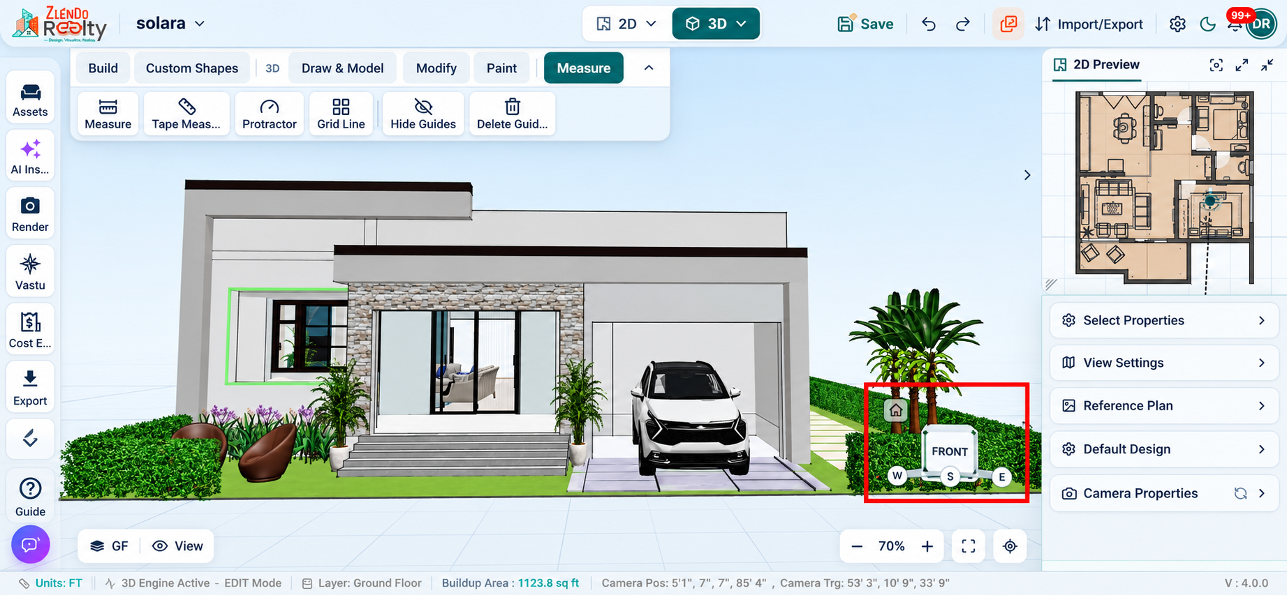
Steps
- Locate the Orientation Compass in the 3D workspace.
- Observe the displayed cardinal directions (N, S, E, W).
- Rotate, pan, or orbit the model as needed.
- Monitor the compass to understand the current viewing angle and orientation.
- Use the compass as a reference when positioning and reviewing the design.
Note: The Orientation Compass updates dynamically as the view changes, helping users maintain accurate directional reference while navigating the model.
Zoom and view control panel #
The Zoom and View Controls allow users to adjust the model’s viewing scale and manage the workspace display.
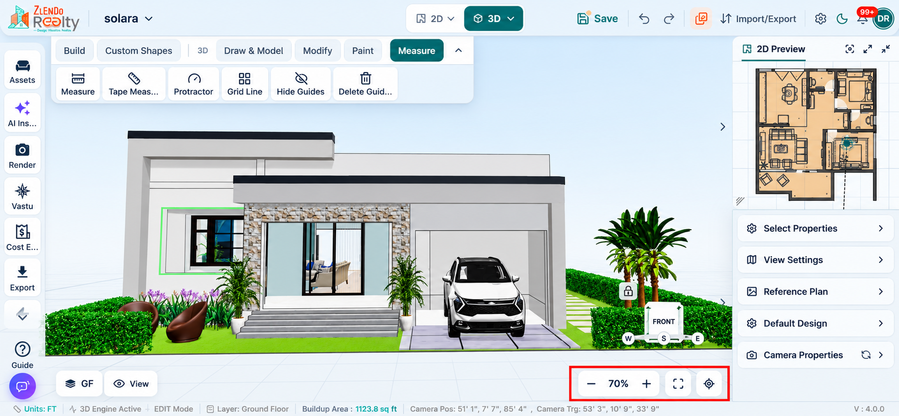
Steps
- Click Zoom Out (-) to decrease the magnification level.
- Click Zoom In (+) to increase the magnification level.
- View the current Zoom Percentage displayed between the zoom controls.
- Click Fit to Screen to automatically adjust the model within the workspace.
- Click View Settings to access additional display and navigation options.
Note: These controls help users quickly adjust the viewing scale and optimize model visibility while working in the workspace.
Layer Plan panel and switching between floors #
The Layer Plan panel allows users to manage project floors and switch between different building levels for design and editing.
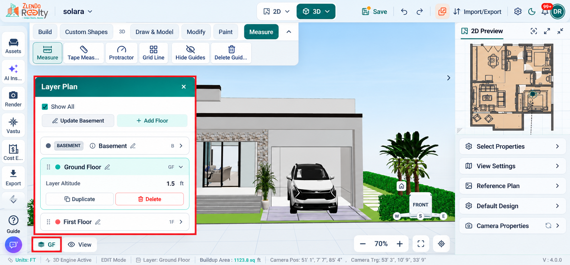
Steps
- Click the Floor Level (GF) button at the bottom-left corner of the workspace.
- The Layer Plan panel opens, displaying all available floors and basements.
- Select a floor such as Basement, Ground Floor, or First Floor to make it the active working level.
- The workspace automatically switches to the selected floor for editing.
- Click Add Floor to create a new floor level.
- Use the Edit option to rename or modify floor properties.
- Review or adjust the Layer Altitude of the selected floor.
- Click Duplicate to create a copy of a floor.
- Click Delete to remove an unwanted floor.
- Enable Show All to display all floors simultaneously in the project.
Note: Selecting a floor from the Layer Plan panel instantly switches the workspace to that level, allowing users to work efficiently across multiple floors within the same project.
View panel #
The View panel allows users to control the visibility of different design elements in the workspace for easier navigation and editing.
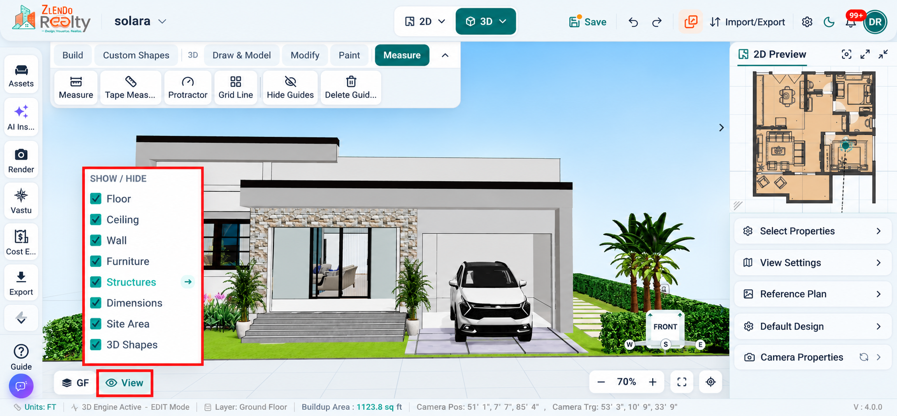
Steps
- Click the View button located at the bottom-left corner of the workspace.
- The Show / Hide panel opens, displaying available visibility options.
- Select or clear the checkbox next to an element to show or hide it.
- Available visibility options include:
- Floor
- Ceiling
- Wall
- Furniture
- Structures
- Dimensions
- Site Area
- 3D Shapes
- The workspace updates immediately based on the selected visibility settings.
- Continue working with only the required elements visible.
Note: The View panel helps declutter the workspace by allowing users to selectively display or hide design components, making it easier to focus on specific parts of the project.
Floor and Ceiling switch panel #
The Floor/Ceiling Switch panel allows users to switch the active working surface between the floor and ceiling for viewing, editing, and placing design elements.
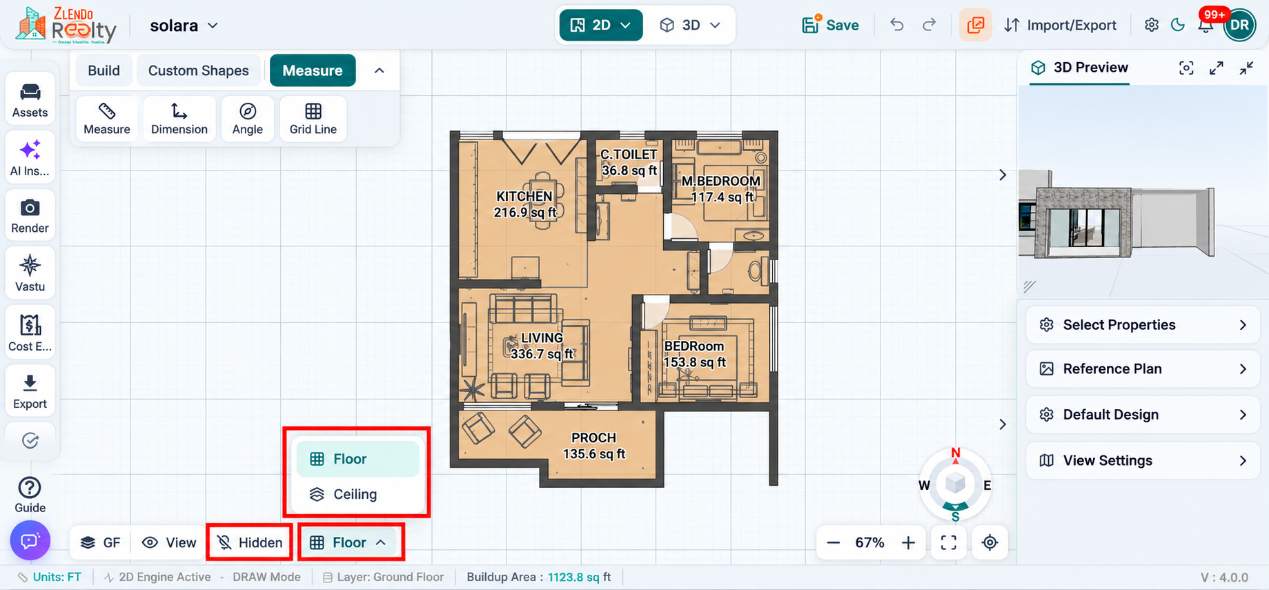
Steps
- Click the Floor drop-down option located next to the Hidden button.
- The panel displays available working surfaces:
- Floor
- Ceiling
- Select Floor to work on floor-level elements and layouts.
- Select Ceiling to work on ceiling-related components and designs.
- The workspace automatically switches to the selected working surface.
- Continue creating or modifying elements on the active Floor or Ceiling view.
Note: Only one working surface can be active at a time. Switching between Floor and Ceiling helps users focus on the relevant design layer without affecting other project elements.
Hidden panel #
The Hidden panel allows users to control the visibility of specific building elements in the active floor.
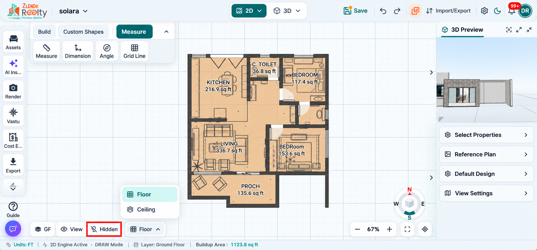
Steps
- Click the Hidden button located at the bottom-left corner of the workspace.
- The visibility panel opens and displays available categories.
- The workspace updates immediately to reflect the selected visibility settings.
- Use these options to focus on specific design components while editing.
Note: The Hidden panel helps simplify the workspace by temporarily hiding selected elements, making it easier to view and modify other parts of the design.
Work space right space properties #
Right Side Collapsible tabs for 3D Preview and Properties #
The 3D Preview and Properties tabs allow users to show or hide the right-side panels to optimize the available workspace.
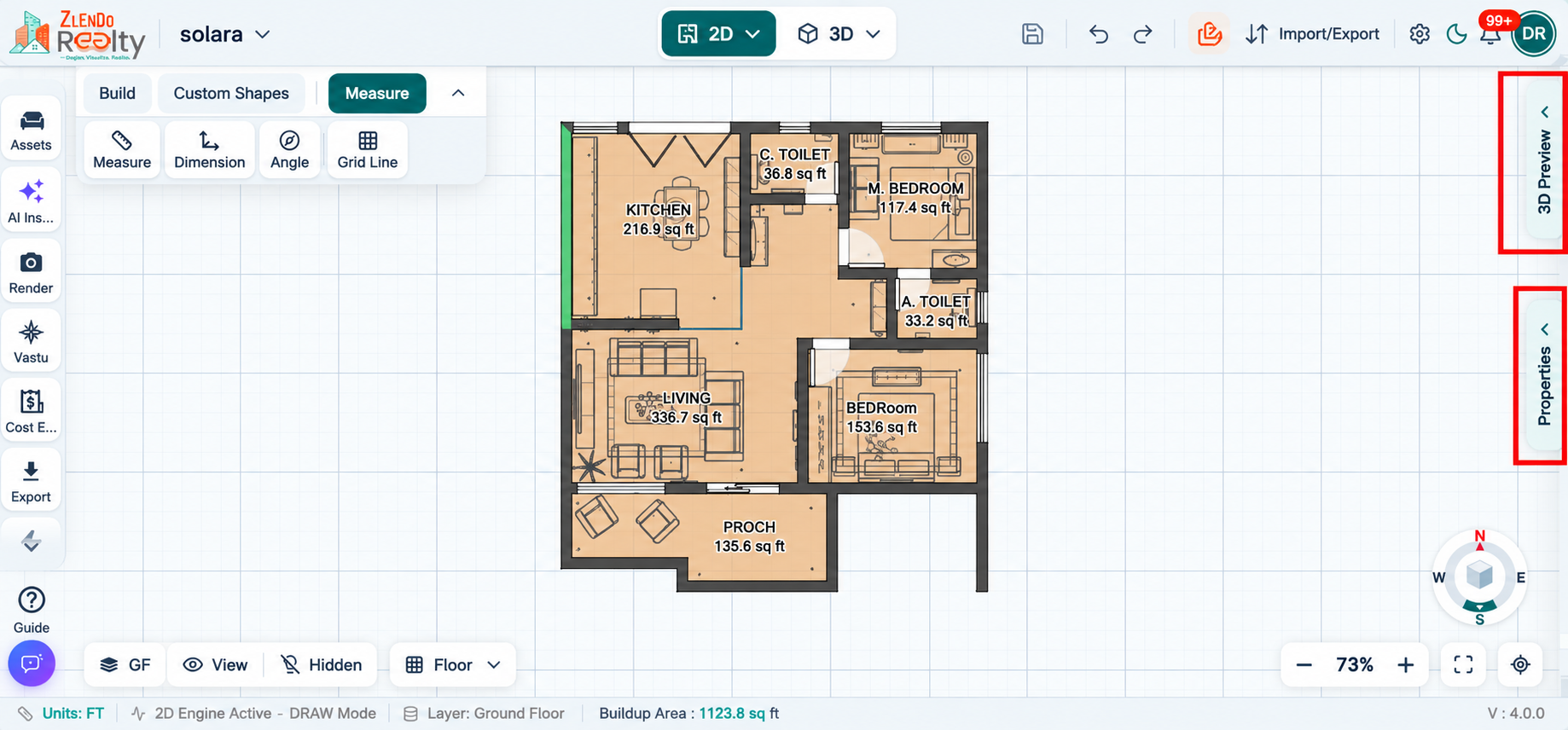
Steps
- Locate the 3D Preview and Properties tabs on the right edge of the workspace.
- Click the 3D Preview tab to expand or collapse the 3D Preview panel.
- Click the Properties tab to expand or collapse the Properties panel.
- When expanded, the panel displays its available options and settings.
- When collapsed, more workspace area becomes available for design and editing.
- Click the tab again at any time to reopen the panel.
Note: Collapsing the 3D Preview and Properties panels provides additional workspace for design activities while keeping these tools readily accessible when needed.
Right-side properties panel displaying 3D Preview #
The Right-Side Properties Panel provides quick access to design visualization, reference tools, display settings, and camera controls within the workspace.
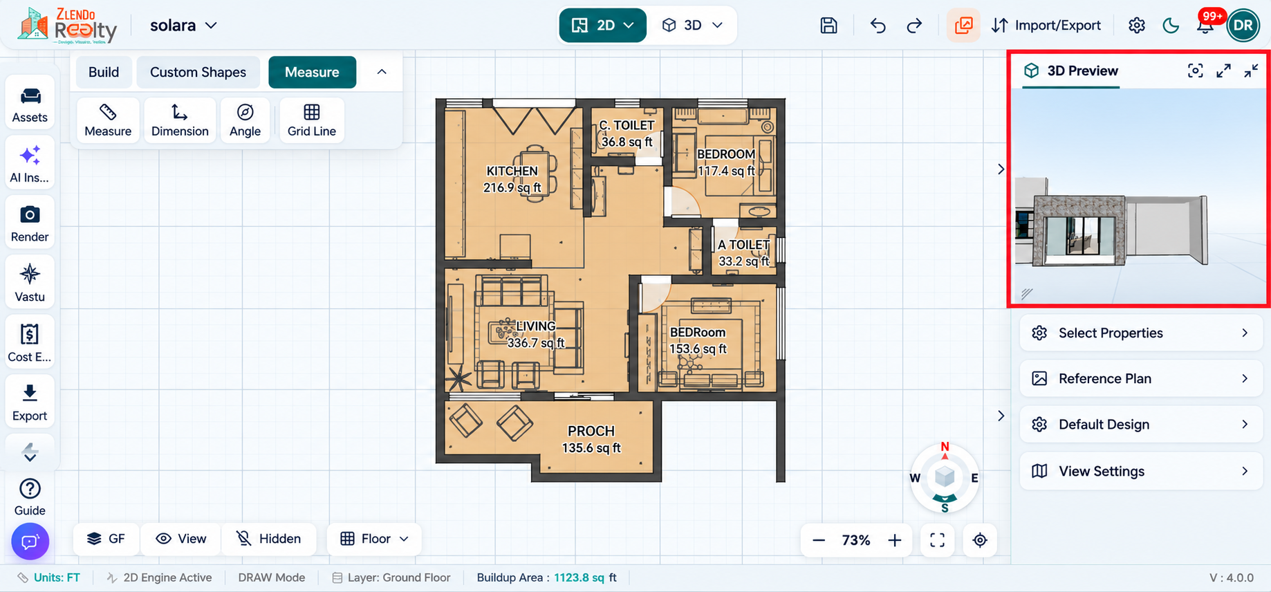
Steps
- Locate the Right-Side Properties Panel in the workspace.
- Use 3D Preview to view a live 3D representation of the design.
- Click Select Properties to view and edit properties of selected elements.
- Open View Settings to configure display and visibility options.
- Use Reference Plan to manage floor plan references.
- Access Default Design settings to apply or manage default design configurations.
- Open Camera Properties to adjust camera and viewing parameters.
- Expand or collapse individual sections as needed while working on the project.
Note: The Right-Side Properties Panel centralizes project visualization, object properties, reference tools, and camera settings, allowing users to manage workspace configurations efficiently without leaving the design area.
Right-side settings panel displaying Select Properties #
The Right-Side Settings Panel provides quick access to project configuration and workspace management tools.
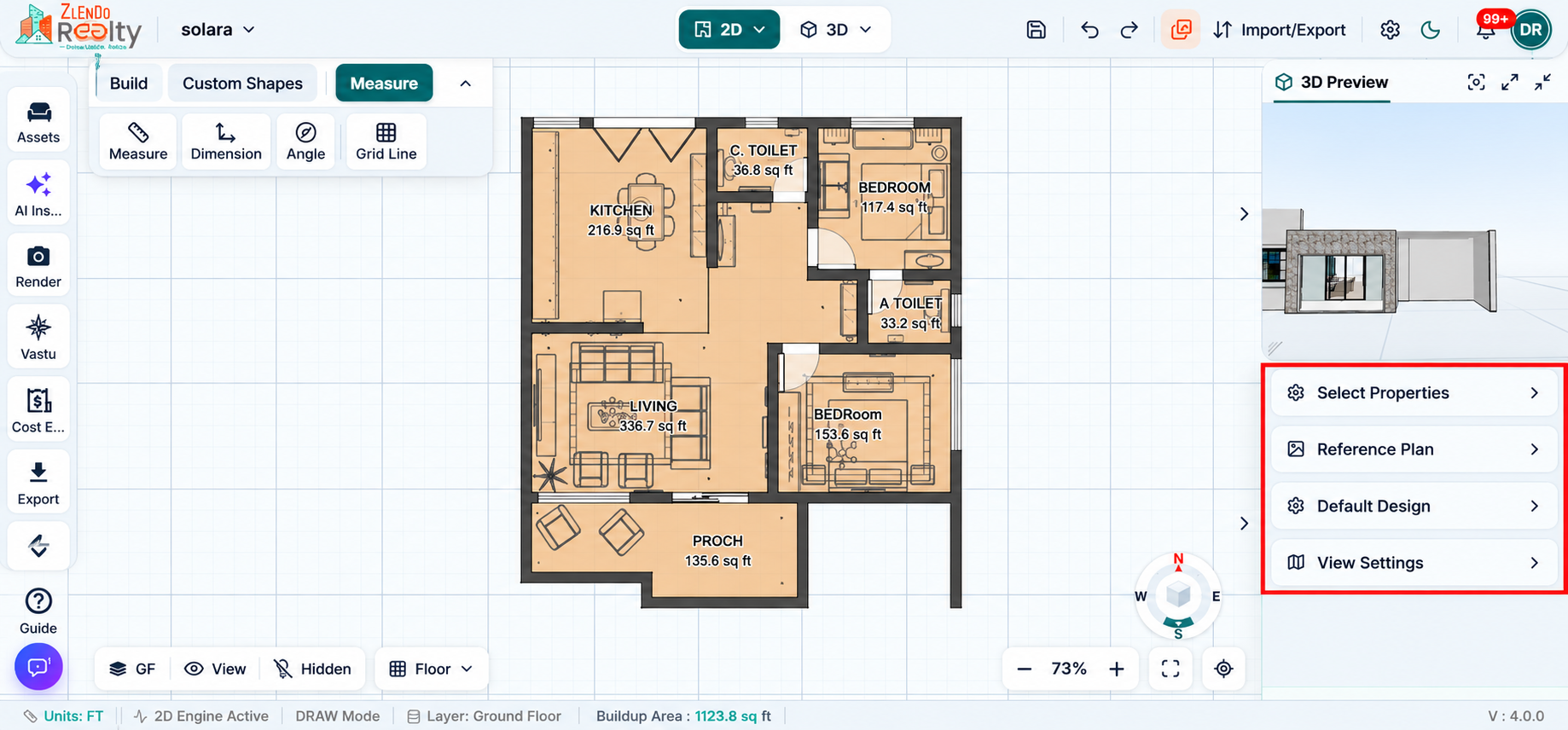
Steps
- Locate the Right-Side Settings Panel in the workspace.
- Click Select Properties to view and modify properties of the selected object.
- Click Reference Plan to manage and view reference floor plans.
- Click Default Design to access default project design settings and configurations.
- Click View Settings to control visibility and display options within the workspace.
- Expand or collapse each section as required while working on the project.
Note: The Right-Side Settings Panel centralizes object properties, reference drawings, design configurations, and view controls, enabling efficient project management without leaving the workspace.


