Version 2.0 Updates in the 2D Editor #
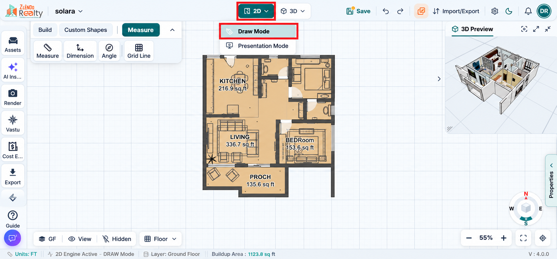
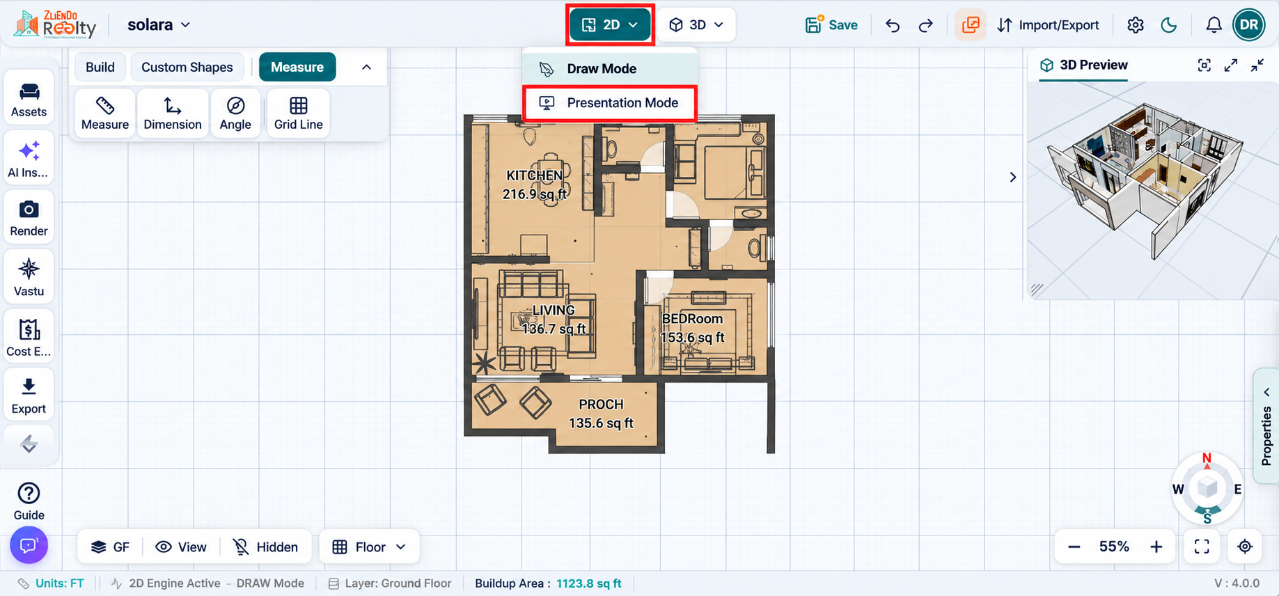
The updated 2.0 version Editor 2D Mode has two options:
- Draw Mode to create and draw designs.
- Presentation Mode to view/present the assets placed in the 2D layout
2D Mode: Drawing #
Build Tool #
Click on Build to access all drawing options. The Build Tool provides the required elements to create and design your floor plan.
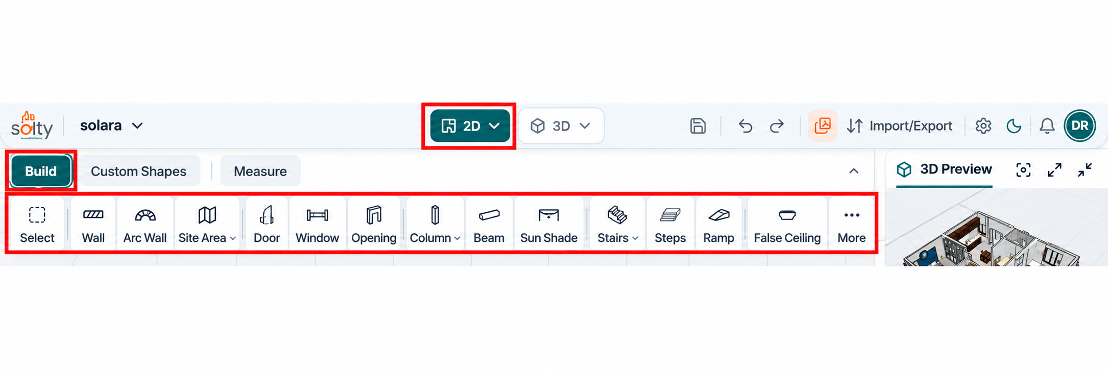
Available options:
- Select – Select and modify existing objects.
- Wall – Draw straight walls.
- Arc Wall – Create curved walls.
- Site Area – Define the site or plot boundary.
- Door – Add doors.
- Window – Add windows.
- Opening – Create wall openings without doors or windows.
- Column – Place structural columns.
- Beam – Add beams.
- Sun Shade – Insert sunshades or canopies.
- Stairs – Create staircases.
- Steps – Add individual steps.
- Ramp – Create ramps for accessibility.
- False Ceiling – Design false ceiling layouts.
- More – Access additional building components and tools.
Note: Use these options to draw and customize the building structure as required.
Drawing walls #
Build Tool –-> Draw Walls –> Straight Line tool (or) Shortcut Key B
On the Build panel, click on Draw Walls. You will see two tools:
✅ Straight Line (for drawing walls)
✅ Site Area (for outlining plot boundaries)
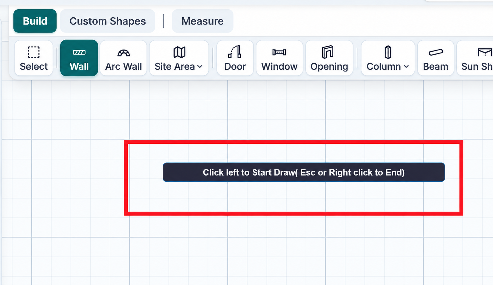
👆 Select the Straight Line tool to begin drawing walls (or) Shortcut Key B.
Start Point & End Point #
Click anywhere on the grid to set the starting point.
Move the cursor in the direction you want the wall and click again to set the endpoint.
A wall segment is created.
Using the Orthogonal / Non-Orthogonal Drawing Option #
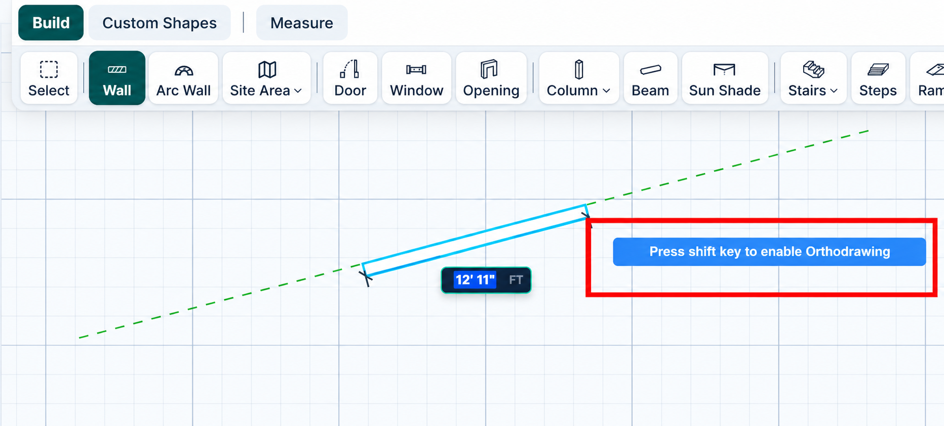
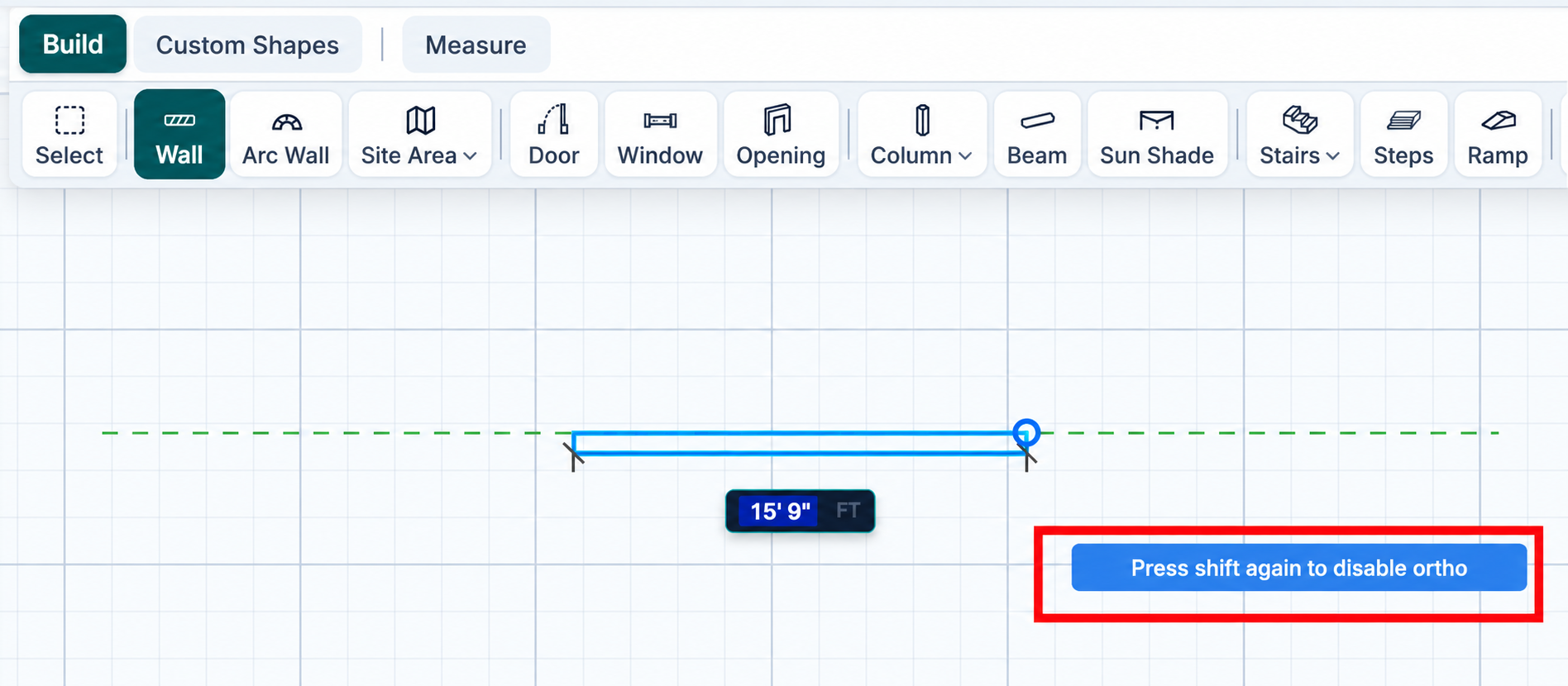
Press the Shift key to enable Orthogonal drawing. This option allows you to draw perfectly straight horizontal or vertical walls
Activate Ortho Mode:
👆 Press the Shift key
When you start drawing using the Straight Line tool, you will see the on-screen message: “Press shift key to enable Orthodrawing”
✔ When Ortho mode is enabled, drawing tool movement is restricted to:
– 0° (horizontal)
– 90° (vertical)
Disable Ortho Mode:
Press the Shift key again
You will see: “Press shift again to disable ortho”
✔ You can now draw at any angle freely
Continue Drawing Connected Walls & Close the Shape to Create a Room #
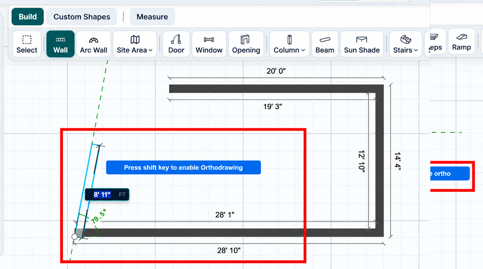
After completing one segment, click again from the previous endpoint and draw in any direction to create connected wall lines.
– The drawing tool maintains continuity for easy room or shape creation.
To complete a room or boundary:
– Extend the line and click back on the starting point
– The system snaps and closes the shape.
Snap & Precision Controls #
Zlendo automatically assists with accurate drawing: When you hover over a wall segment, the snap points will usually change your cursor or display a tiny geometric icon to show you what you are locking onto.
Common Snap Point Indicators
✛ Start/Endpoint Snap : Snaps to the very beginning or end of a wall segment.
◼Midpoint Snap: Automatically finds the exact center-point of that specific wall segment
⁜ Intersection Snap: Helps connect walls precisely at corners
📏 Real-time Measurement: Wall length is displayed while drawing
📐 Angle Indicator: Shows the angle of the connected walls
📌 On-Screen Drawing Prompts
Dynamic length labels (e.g., 18’1″ FT)
Angle indicators (e.g., 77.7°)
Snap points such as “Intersection” / “Midpoint”
Wall Editing Tips
✅ Use Undo / Redo buttons (top ribbon) if needed
✅ Zoom and pan to adjust your view while drawing
2D Drawing Best Practices #
✅ Use Shortcut Key B to draw a wall
✅ Use Shift (Ortho Mode) for straight walls and clean layouts
✅ Use Free drawing (Ortho OFF) for Angled designs or irregular shapes
✅ Watch for snap indicators to ensure accuracy
✅ Check live measurements to match real-world dimensions
Drawing Arc Walls #
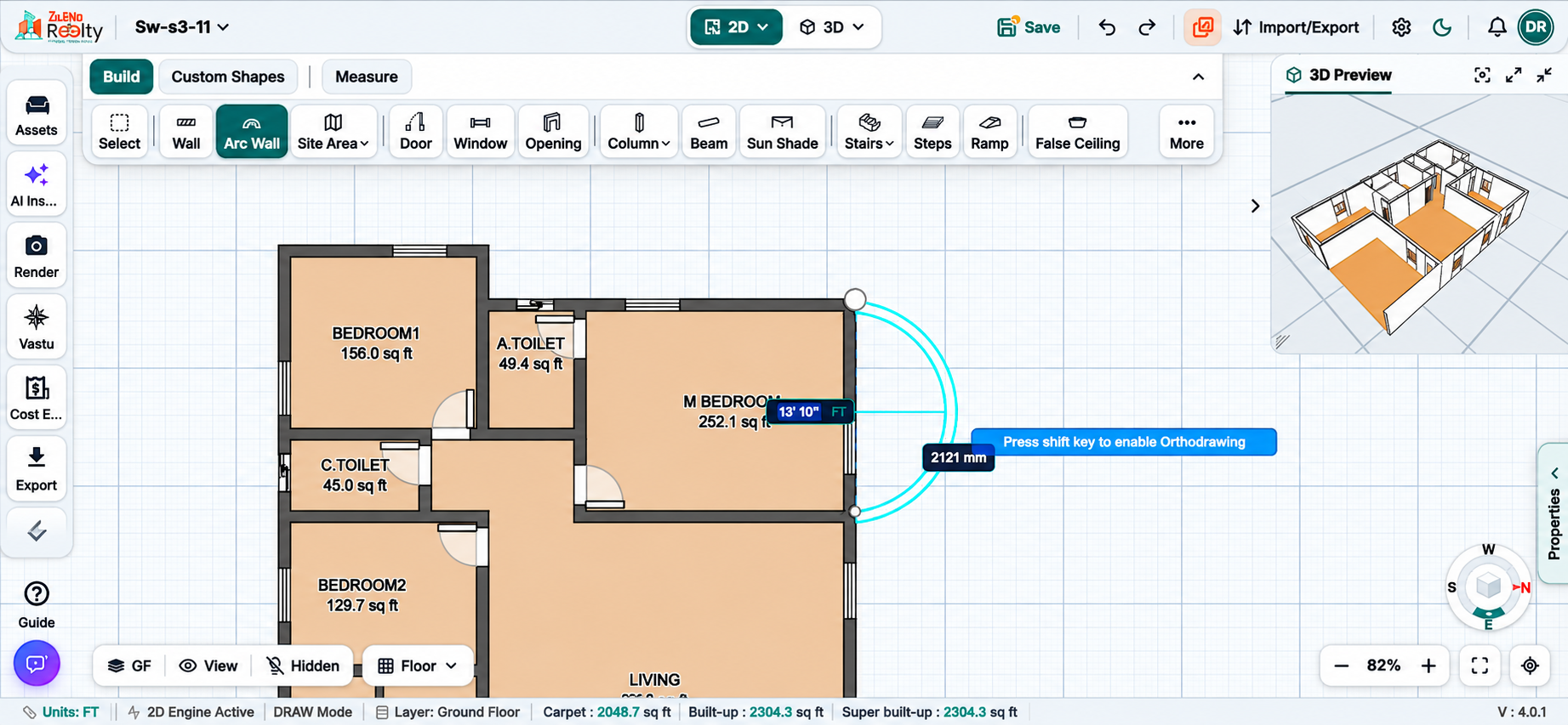
Open the Arc Wall Tool #
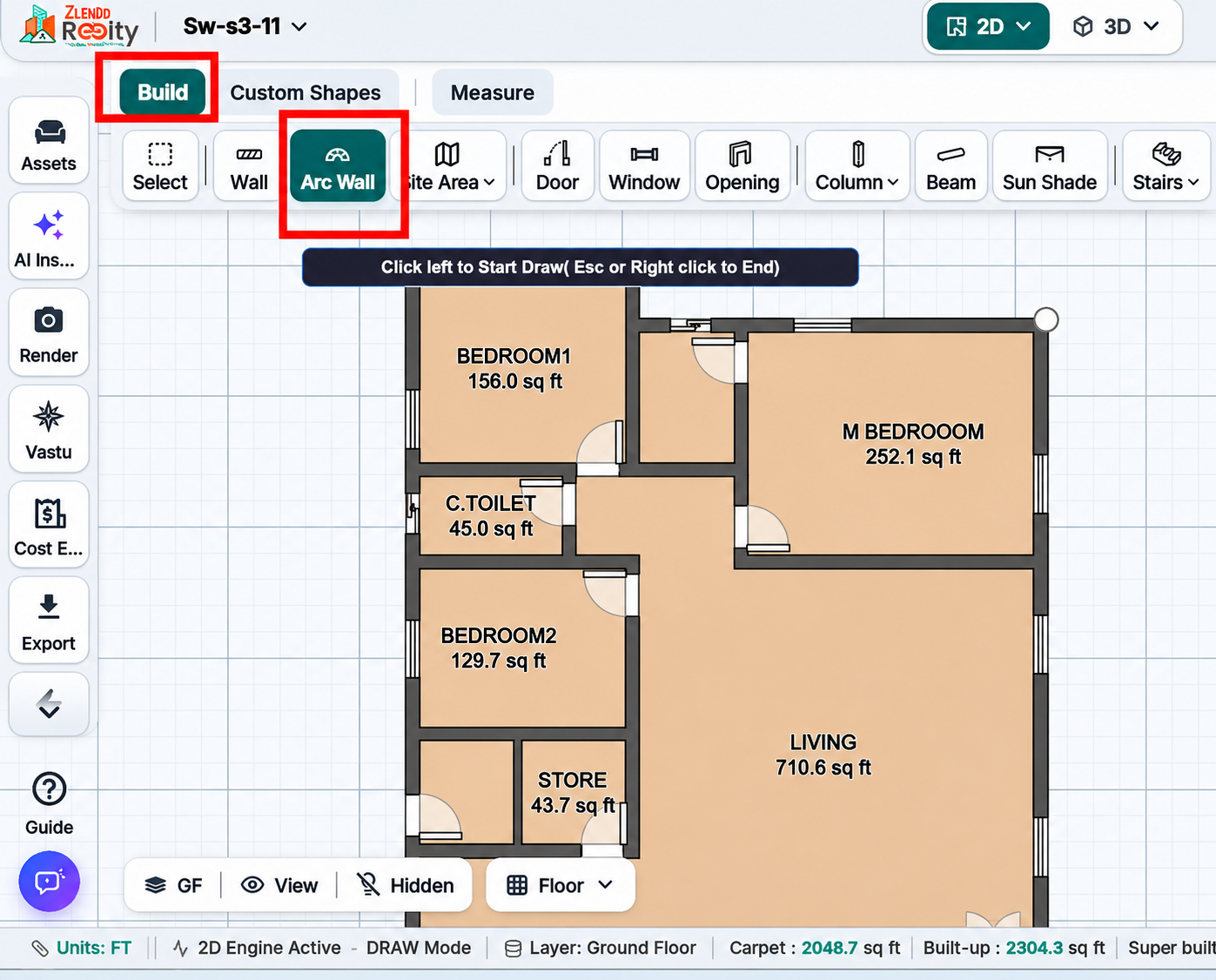
- Go to Build Tool → Draw Walls → Arc Wall.
- Or press H (shortcut key).
Draw an Arc Wall #
- Click on the grid to set the starting point of the arc.
- Move the cursor and click to set the ending point.
- Move the cursor outward or inward to define the arc curvature (radius).
- Click again to complete the arc wall.
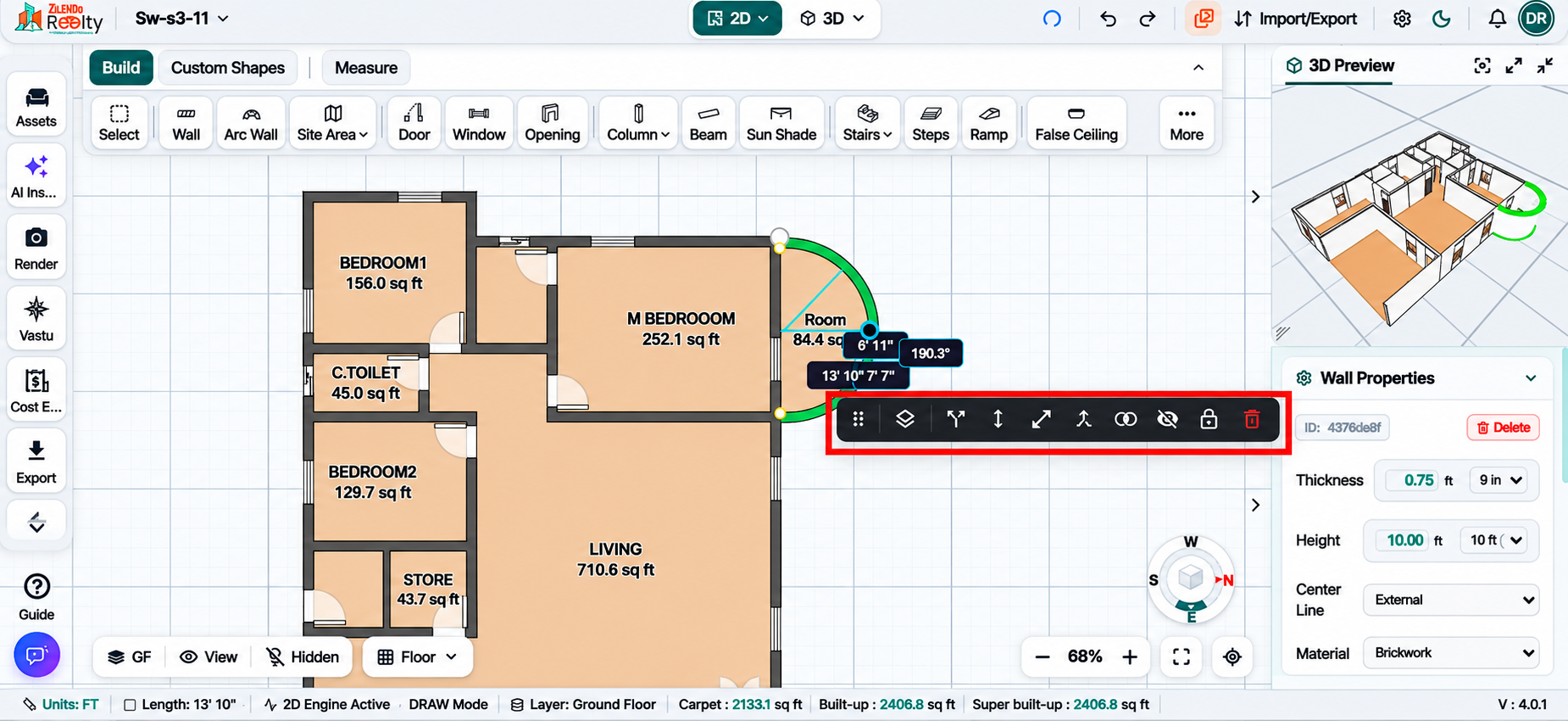
Arc Wall Controls #
- Adjust the cursor position to increase or decrease the curve radius.
- Arc walls can be drawn as Convex Arc (curves outward) or Concave Arc (curves inward).
- Real-time preview helps visualize the arc before placement.
Continue Drawing Connected Walls #
- After completing an arc segment, continue drawing from the endpoint.
- Arc walls can connect with straight walls and other arc walls.
- Snap points help create smooth and accurate connections.
Create a Closed Room #
- Draw additional wall segments and return to the starting point.
- The system automatically snaps and closes the shape to form a room.
Snap Features #
- ✛ Endpoint Snap: Snaps to wall start/end points.
- ◼ Midpoint Snap: Snaps to the center of a wall.
- ⁜ Intersection Snap: Snaps to wall intersections and corners.
- Tangent Snap: Helps create smooth transitions between arc and straight walls.
Drawing Assistance #
- Real-time Radius Display shows the arc radius while drawing.
- Arc Length Measurement updates dynamically.
- Angle Indicator displays the sweep angle of the arc.
- Snap labels appear automatically when available.
Editing Tips #
- Use Undo/Redo from the top ribbon if required.
- Use Zoom and Pan for precise arc placement.
- Select the arc wall to modify its radius or position later.
Best Practices #
- Press H to quickly start drawing arc walls.
- Use arc walls for curved rooms, entrances, facades, and feature walls.
- Watch the snap indicators for accurate connections.
- Verify radius and arc measurements before finalizing.
- Combine straight and arc walls for complex floor plan designs.
Drawing Site Areas #
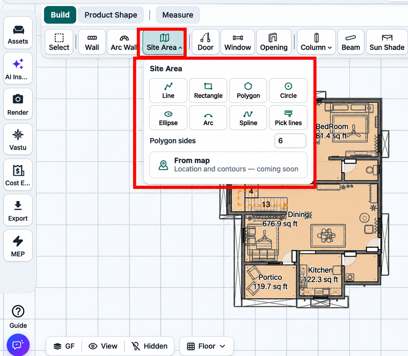
Build Tool → Site Area (or) Select a Site Area shape from the Site Area menu.
On the Build panel, click on Site Area. You will see the following tools:
- Line (for creating custom site boundaries)
- Rectangle (for rectangular site areas)
- Polygon (for multi-sided site boundaries)
- Circle (for circular site areas)
- Ellipse (for elliptical site areas)
- Arc (for arc-shaped site boundaries)
- Spline (for freeform curved boundaries)
- Pick Lines (for creating site areas from existing lines)
Select the required Site Area tool to begin creating the plot boundary.
Site Area: Line Tool — Start Point & End Point #
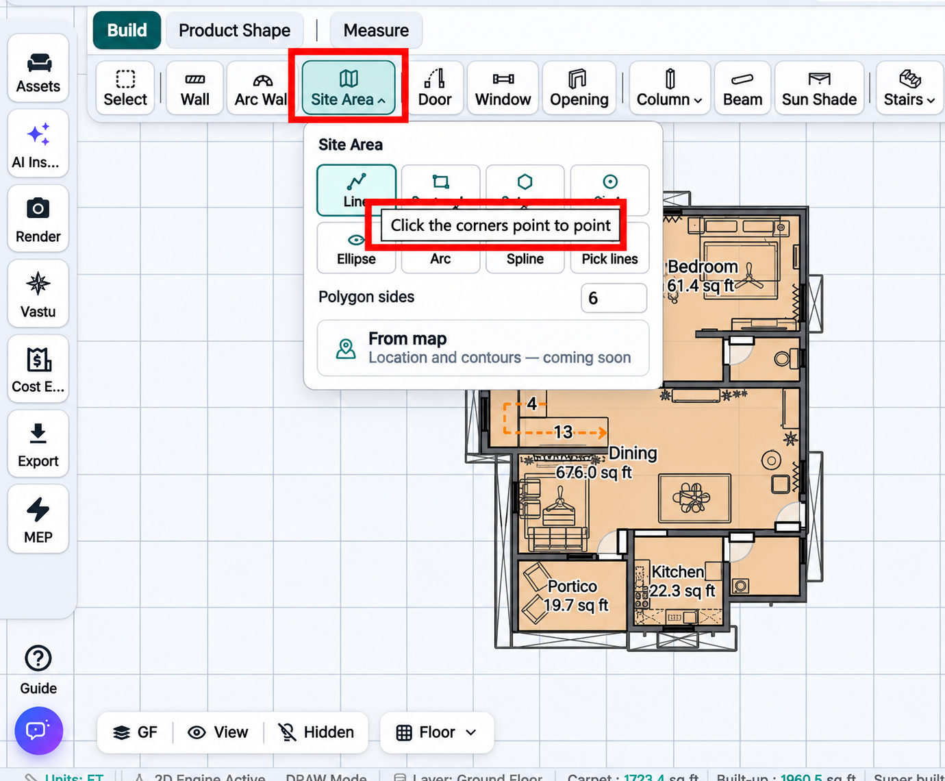
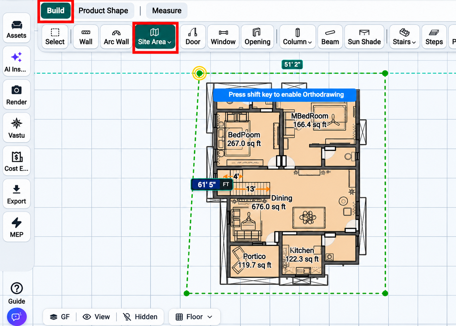
- Click anywhere on the grid to set the starting point.
- Move the cursor in the desired direction and click again to set the endpoint.
- A site boundary segment is created.
Drawing Connected Site Boundaries #
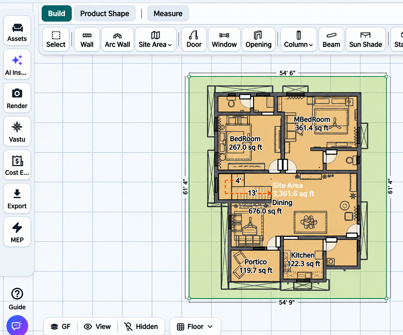
- After completing one segment, click again from the previous endpoint and continue drawing connected boundary lines.
- The drawing tool maintains continuity for easy site boundary creation.
- To complete a site area, continue drawing until you reach the starting point.
- The system automatically snaps and closes the boundary.
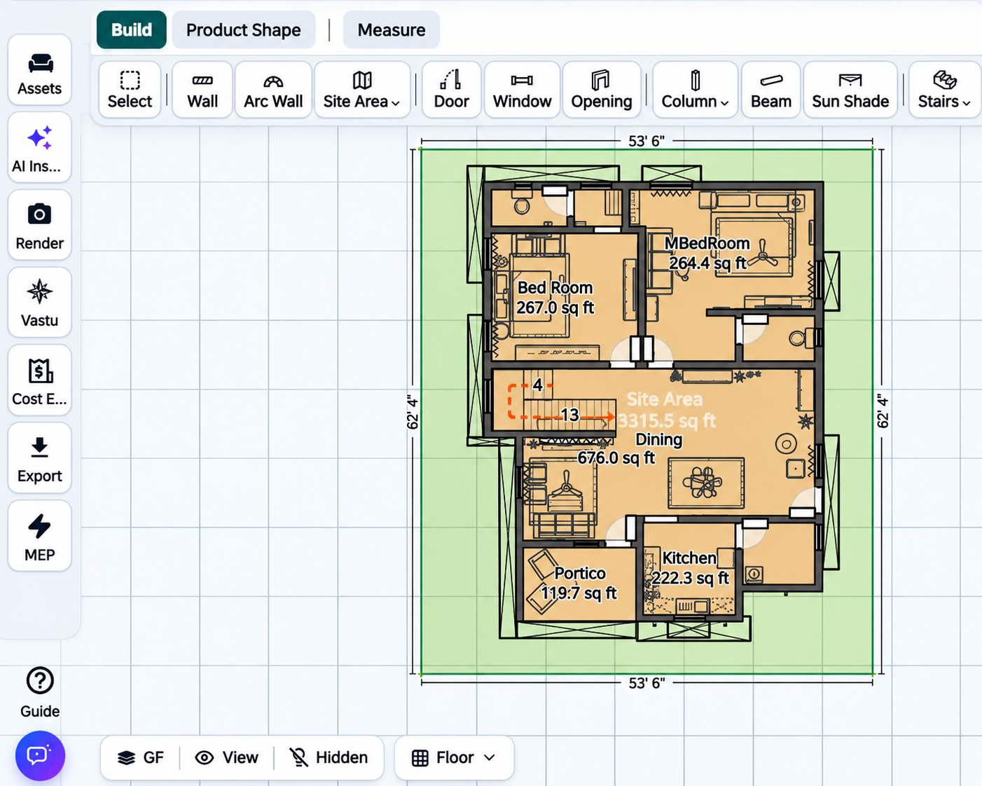
Rectangle Site Area #
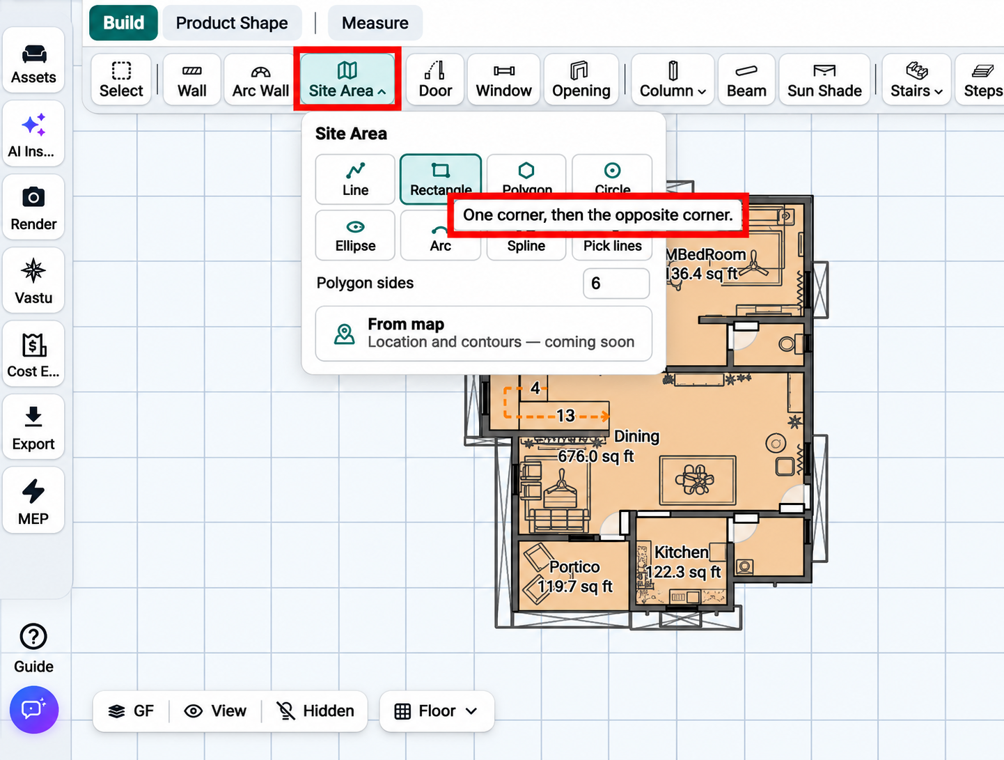
- Select Rectangle from the Site Area menu.
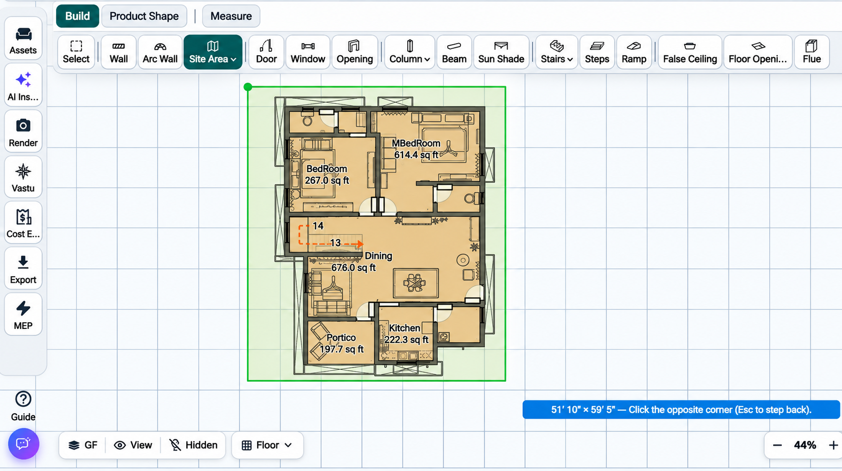
- Click to set the first corner.
- Move the cursor and click again to set the opposite corner.
- A rectangular site area is created.
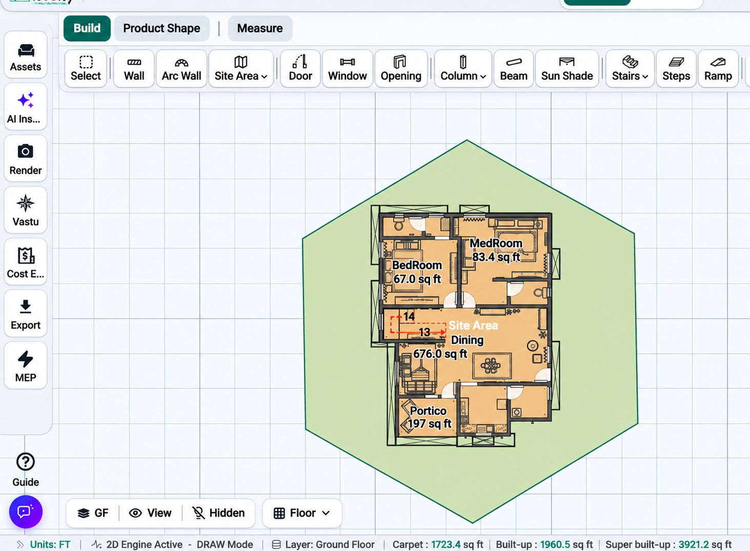
Polygon Site Area #
- Select Polygon from the Site Area menu.
- Set the required Polygon Sides value.
- Click to place the polygon center.
- Move the cursor and click again to define the polygon size.
- A polygon site area is created automatically.
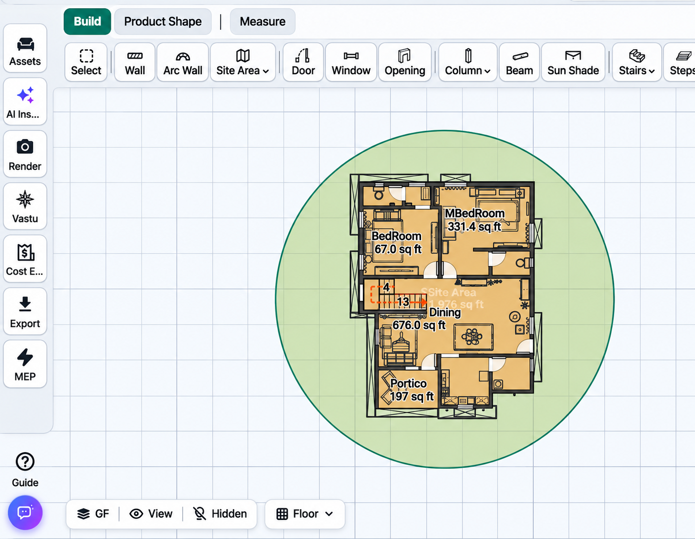
Circle Site Area #
- Select Circle from the Site Area menu.
- Click to define the center point.
- Move the cursor outward and click again to define the radius.
- A circular site area is created.
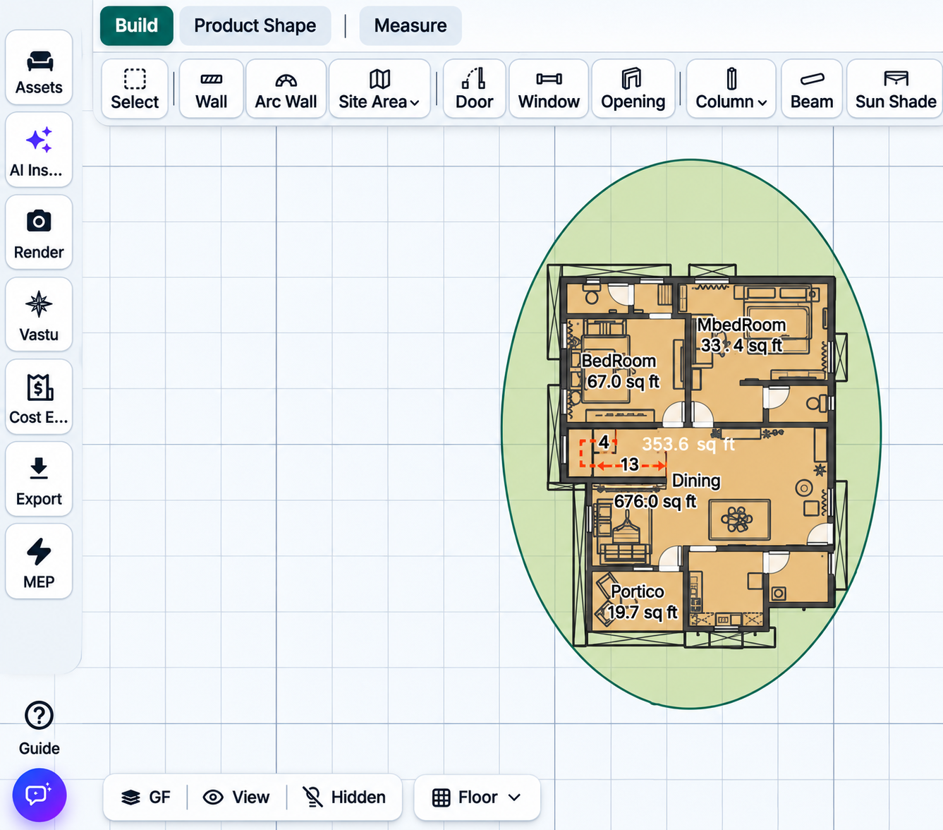
Ellipse Site Area #
- Select Ellipse from the Site Area menu.
- Click to define the center point.
- Set the major and minor axis dimensions by moving the cursor and clicking.
- An elliptical site area is created.
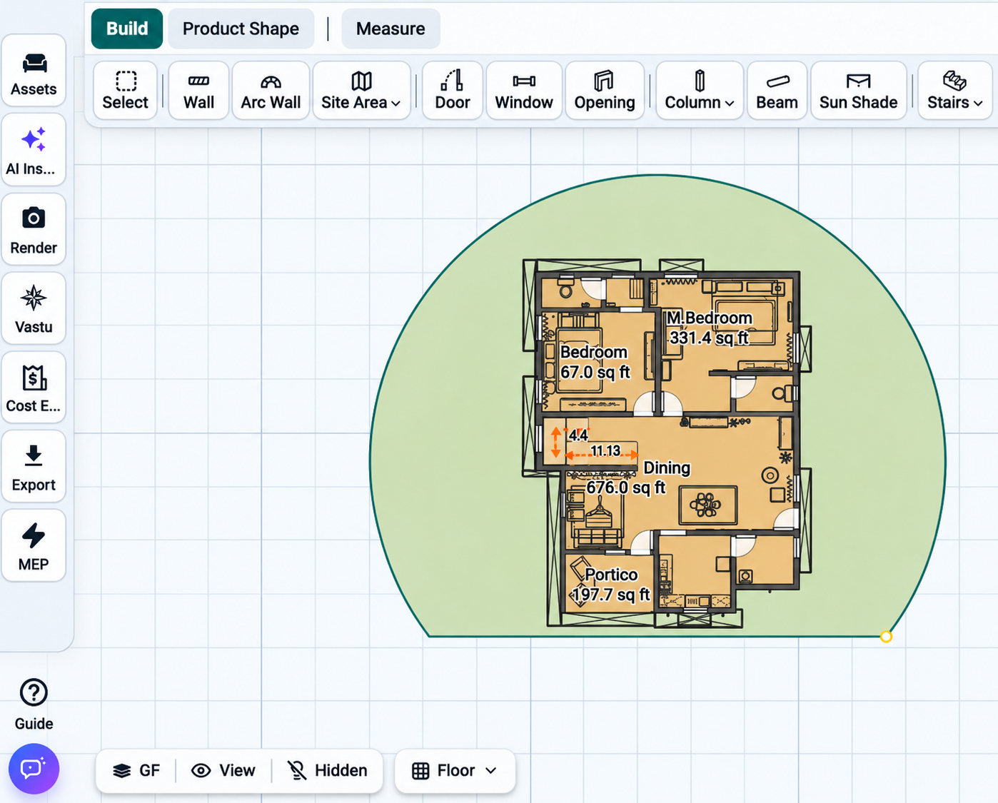
Arc Site Area #
- Select Arc from the Site Area menu.
- Click to set the start point.
- Click again to set the endpoint.
- Move the cursor to define the curvature and click to complete the arc.
- An arc-shaped boundary segment is created.
Spline Site Area #
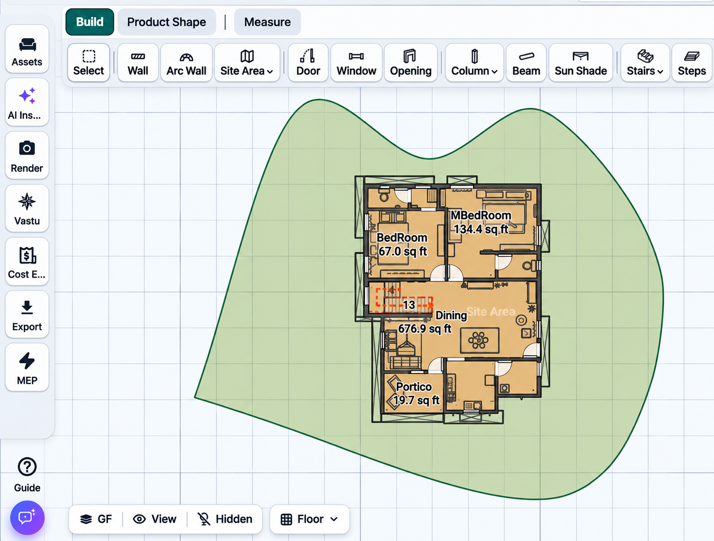
- Select Spline from the Site Area menu.
- Click multiple points to create a smooth curved boundary.
- Double-click to finish the spline.
- A freeform curved site boundary is created.
Pick Lines #
- Select Pick Lines from the Site Area menu.
- Hover over existing lines or boundaries.
- Click the required lines to generate the site area automatically.
Snap & Precision Controls #
Zlendo automatically assists with accurate drawing. When you hover over a boundary segment, snap points will appear to help with precise placement.
Common Snap Point Indicators #
- ✛ Start/Endpoint Snap: Snaps to the beginning or end of a boundary segment.
- ⁜ Intersection Snap: Helps connect boundaries accurately at intersections.
- Center Snap: Helps align circles, ellipses, and polygons accurately.
- Real-time Measurements: Displays dimensions while creating site areas.
- Angle Indicator: Shows boundary angles during drawing.
Site Area Editing Tips #
- Use Undo / Redo buttons (top ribbon) if needed.
- Zoom and pan to adjust your view while creating site areas.
- Select a site area to modify its dimensions, shape, or position.
2D Drawing Best Practices #
- Use the appropriate Site Area tool based on the plot shape.
- Use Rectangle and Polygon tools for regular site layouts.
- Use Arc, Ellipse, and Spline tools for irregular site boundaries.
- Watch for snap indicators to ensure accuracy.
- Check live measurements while creating site areas.
- Close all boundaries properly to create a valid site area.
Adding Doors / Windows / Openings #
After making a room(s), the next step is to add items like doors & windows to rooms.
Build Tool –> Doors & Windows
From the Build tool list, click on “Doors & Windows” (highlighted section). You will see three options:
✔ Door
✔ Window
✔ Opening (empty cut-outs like passages)
Select an Element #
Choose the element you want to add from the Build Tool:
✔ Click Door to place doors
✔ Click Window to add windows
✔ Click Opening for empty wall cutouts
Placing the Door or Window #
👆 Move your cursor over a wall and click on the desired location to place it.
The element will automatically snap to the wall.
📌 Placing Tips
✔ The element aligns to the wall direction
✔ Snap points help ensure precise positioning
Adjust Placement
After placing, you can:
✔ Drag along the wall to reposition
✔ Snap to edges or center for accurate alignment
Doors & Windows Best Practices: #
✅ Place doors near wall edges or room entries
✅ Use Snap ON for precise alignment
✅ Adjust height and thickness based on design needs
✅ Maintain consistent alignment (Center/Inside/Outside) for clean layouts
Adding Structures #
Build –> Add structures
👆 Click on any icon from the library of structural elements
✔ Column
✔ Circle Column
✔ Beam
✔ Sun Shade
✔ Staircases (Straight, L, U, Winder)
✔ Custom Staircases
✔ Steps
✔ Flue
✔ Ramp
✔ False Ceiling
✔ Floor Opening
How to Use Structure Types #
| Structure Type | Placement | Best Practices & Details |
| Columns | Inside rooms or at corners for structural support | Use circle columns for rounded designs |
| Beams | Between walls or columns | Align horizontally for support structures |
| Staircases & Steps | Based on layout flow and access requirements | Select type based on layout: Straight, L-shape, U-shape, or Winder. Position carefully to ensure proper access flow |
| Custom Staircase | Customized locations based on project requirements | Create unique staircase designs with tailored shapes and dimensions to fit specific layouts. |
| Ramp | In entry/exit areas | Use for smooth elevation transitions |
| Sun Shade & False Ceiling | Above openings or rooms | Add for architectural detailing |
| Floor Opening | Between floors where vertical access is needed | Create openings for staircases, atriums, elevators, or other vertical connections between levels. |
Placing the Structure #
Click on the structure you want to add.
Move your cursor over the layout grid or inside rooms.
Click again to place the structure at the desired location.
Adjust Position #
Click and drag the placed structure to:
Reposition within the layout
Align with walls, corners, or center points
Adding Multiple Structures #
Continue selecting and placing additional elements as required.
Combine different structure types for a complete design.
📌 Structure: Placement Behavior
✔ Structures align with the grid for accuracy
✔ Some elements (like beams) may align with walls automatically
Structure: Best Practices: #
✅ Use Grid & Snap for precise alignment
✅ Place columns at load points (corners/intersections)
✅ Align beams with walls or columns
✅ Ensure staircases have adequate space
✅ Maintain consistency in dimensions and alignment
Drawing in 2D Summary #
| Mode / Action | Description |
| 2D Mode | Start in 2D view |
| Draw Walls | Use Straight line Wall tool (Shortcut Key B) |
| Doors & Windows | Select and place on walls |
| Structures | Add columns, stairs, beams |
| Adjust Item Properties | Use the right-side panel to refine size and alignment of any item |
| Review | Use grid, snap, zoom |
Pro Tips for Efficient Designing #
✔ Always start with walls before adding elements (Shortcut Key B)
✔ Use Shift (Ortho Mode) for clean layouts
✔ Keep Snap ON for accuracy
✔ Maintain consistent dimensions
✔ Plan circulation spaces (doors, stairs) properly
✔ Regularly check layout in both 2D & 3D


